Reliability analysis and test methods of lead-free solder joints
Oct 16, 2021
At present, the demand for lead-free soldering in the electronics industry is becoming more and more urgent, which has had a huge impact on the entire industry. Lead-free solder has begun to gradually replace lead solder, but lead-free technology will inevitably bring new problems to the reliability of solder joints due to differences in solders and adjustment of soldering process parameters.
Therefore, the reliability of lead-free solder joints has also been paid more and more attention. This article describes the failure modes of solder joints and the factors that affect the reliability of lead-free solder joints. At the same time, it introduces the reliability test methods of lead-free solder joints.
Failure mode of solder joint
The reliability experiment work of solder joints includes reliability experiment and analysis. On the one hand, the purpose is to evaluate and appraise the reliability level of integrated circuit devices and provide parameters for the reliability design of the whole machine; on the other hand, it is to improve the reliability of solder joints. reliability.
This requires the necessary analysis of failed products to find out the failure mode and analyze the cause of the failure. The purpose is to correct and improve the design process, structural parameters, welding process, etc. The failure mode of the solder joint is very important for the prediction of cycle life. Establish the basis of its mathematical model. Three failure modes are described below.
#1 Solder joint failure caused by welding process
Some unfavorable factors in the welding process and the subsequent improper cleaning process may cause the failure of the solder joints. The reliability problems of SMT solder joints mainly come from the production assembly process and the service process. In the production and assembly process, due to the limitations of equipment conditions such as pre-welding preparation, welding process and post-welding inspection, as well as human errors in the selection of welding specifications, welding failures such as false welding, solder short-circuit and Manhattan phenomenon are often caused.
On the other hand, during use, due to unavoidable shocks, vibrations, etc., mechanical damage to the solder joints will also be caused. For example, the rapid changes in heat and cold during wave soldering will cause a temporary temperature difference on the components, causing the components to withstand thermo-mechanical stress. . When the temperature difference is too large, stress cracks will occur in the ceramic and glass parts of the component. Stress cracking is an unfavorable factor that affects the long-term reliability of solder joints.
At the same time, during the assembly process of thick and thin-film hybrid circuits (including chip capacitors), there are often gold and silver corrosion phenomena. This is because the tin in the solder forms a compound with the gold and silver in the gold-plated or silver-plated pins, which reduces the reliability of the solder joints. Excessive ultrasonic cleaning may also affect the reliability of solder joints.
#2 Failure caused by aging
When the molten solder contacts the clean substrate, intermetallic compounds (intermetallicCompounds) are formed at the interface. During the aging process, the microstructure of the solder joints will be coarsened, and the IMC at the interface will continue to grow. The failure of solder joints partly depends on the growth kinetics of the IMC layer. Although the intermetallic compound at the interface is a sign of good welding, as its thickness increases during service, it will cause microcracks and even fracture in the solder joints.
When its thickness exceeds a certain critical value, the intermetallic compound will show brittleness, and due to the thermal expansion mismatch between the various materials that make up the solder joint, the solder joint will experience periodic strain during the service process, and the deformation is sufficient It will lead to failure when it is too large. Studies have shown that the addition of trace rare earth element lanthanum to the Sn60/Pb40 solder alloy will reduce the thickness of the metal compound, thereby increasing the thermal fatigue life of the solder joint by 2 times and significantly improving the reliability of the surface assembly solder joint.
#3 Failure caused by thermal cycling
Under the service conditions of electronic devices, the periodic on-off of the circuit and the periodic change of the ambient temperature will cause the solder joints to undergo a temperature cycle process. The thermal expansion mismatch of the packaging materials will cause stress and strain in the solder joints. For example, the coefficient of thermal expansion (CTE) of the chip carrier material A1203 ceramic in SMT is 6&TImes;10-6℃-1, while the CTE of the epoxy resin/glass fiber substrate is 15&TImes;10-6℃-1.
When the temperature changes, the solder joints will withstand a certain amount of stress and strain. Generally, the strain tolerated by the solder joint is 1% to 20%. In the THT process, the flexible pins of the device will absorb most of the strain caused by thermal mismatch, and the strain that the solder joints really bear is very small. In SMT, the strain is basically borne by the solder joints, which will lead to the initiation and propagation of cracks in the solder joints, and ultimately fail.
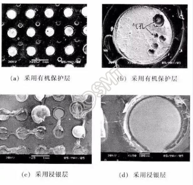
The organic protective layer decomposes and generates gas when passing through the reflow oven. These gases are too late to be discharged and form pores near the outside. When the solder joint is subjected to external force, stress concentration occurs at the pores and micro-cracks are formed. The micro-cracks then expand and grow, and eventually cause the solder joint to break, thus reducing the strength of the solder joint.
Since the solder joints crack and cause failure due to thermal stress caused by the mismatch of the thermal expansion coefficient, improving the thermal matching of the leadless component and the substrate material is most likely to be the first concern of people. At present, 42% Ni-Fe alloy (CTE=5&TImes;10-6℃-1), Cu-36% Ni-Fe alloy (indium tile alloy), Cu-Mo-Cu and quartz fiber composite materials have been researched and developed. The material, in which the Cu-Indium tile-Cu composite substrate changes the proportion of each component, the weldment with this substrate lead-soldered after 1500 thermal shock tests, no solder joint failure.
In addition, it has also developed a technology to compound a stress-absorbing layer with greater elasticity on the printed circuit board to absorb the stress caused by thermal mismatch and other aspects, which have also achieved relatively good results. However, the process of the new substrate material is complicated, the price is relatively expensive, and its practicability is limited to a certain extent.