The mounting mechanism of SMT patch machine
Jan 23, 2024
Preface
The placement technology in SMT production refers to picking up chip components from the packaging in a certain way and accurately placing them on the designated position on the PCB. The more specific name of "SMT" is usually also used. Theoretically, the placement process can be realized by two methods: manual and machine. With the increasing complexity of electronic products and the miniaturization of chip components, as well as the continuous advancement of production cost efficiency control in the industry, manual placement has long withdrawn from the mainstream field of mass-scale production. Now, even in the laboratory, manual placement is difficult to meet the requirements of new component assembly. Therefore, the placement technology we discussed is completed through various placement machines with different functions and performances. Mounting, a seemingly simple industrial process, is actually an extremely complex process technology that combines machinery, light, and electricity, software/hardware coordination, equipment, technology, and management.
1. Basic process of placement
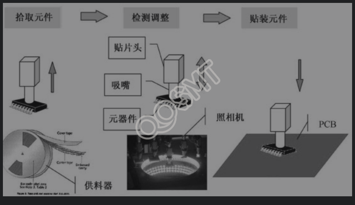
In placement technology, we regard printed circuit board transmission (including the entry of the circuit board to be mounted and the circuit board leaving the placement area after placement), support and identification positioning as necessary before and after processes for placement, leaving Discussed in detail in later relevant chapters. In this chapter, we only discuss pure "placement" - including the three basic processes of picking up components, detecting and adjusting, and component placement, as shown in the figure below.
2. Pick up components
Picking up components refers to picking up chip components from the packaging in a certain way. In this process, the time and accuracy of picking are key. Factors that affect this process include the tools and methods of picking, the method of component packaging, and the related performance of the components themselves.
1. Picking tools and methods
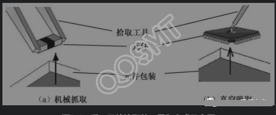
So far, the tools and methods of machine picking are still similar to manual picking: there are two basic modes: mechanical grabbing and vacuum suction. However, the complexity of machine picking tools and the speed of the process are unmatched by manual picking, as shown in the figure below.
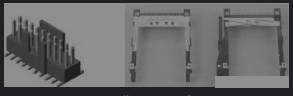
The mechanical grasping method shown in (a) above, which is similar to manually using tweezers to grasp components, is basically not used in machine placement. Almost all placement machines use vacuum to pick up components. Only in special circumstances, for example, for some larger and special-shaped components, as shown in the figure below, it may be a more cost-effective method to use mechanical chuck gripping for placement.
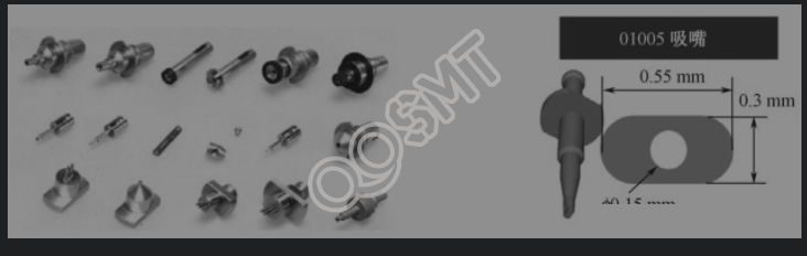
In the placement machine, vacuum suction of components is completed through the component pickup tool - suction nozzle. Since components vary greatly in size and shape, general placement machines are equipped with a variety of suction nozzles. The picture below shows the nozzles configured on a placement machine. These nozzles are stored in the nozzle box. During the placement work, the placement head selects the corresponding nozzles according to the instructions of the control computer, and then puts them back after completing the placement task. Nozzle box.
2. Feeder and component packaging methods
Feeder, also known as feeder or "Feeder" (transliteration of the English name Feeder), is an important component in placement technology that affects placement capacity and production efficiency. It is also the most important accessory of the placement machine. As for some placement machine models, the number of feeders that can be accommodated is directly used as a symbol. Different types of surface mount components use different packaging, and different packaging requires corresponding feeders. In the placement machine, the components in the package are provided to the nozzle through the feeder according to the instructions of the placement machine. Therefore, the packaging form and quality of the feeder and surface mount components have an impact on the pick-up component process. important role.
3. Mounting performance of components
Electronic components have many performance parameters, among which the main ones related to placement are:
(1) Appearance length and width dimensions
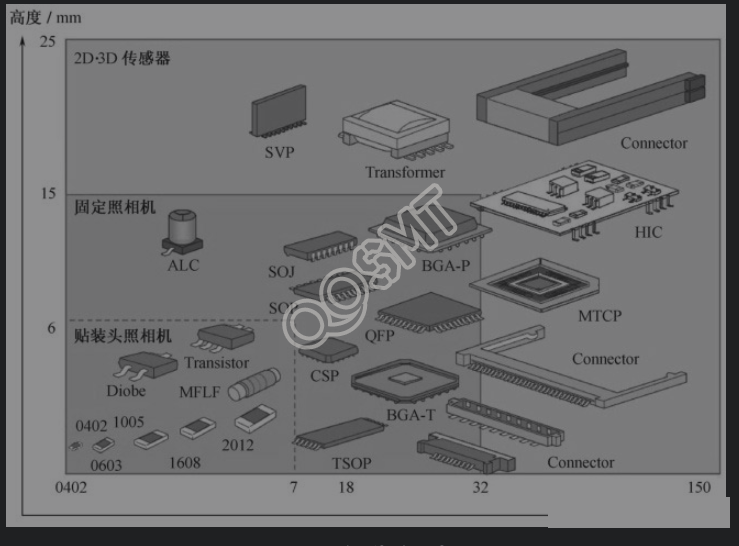
The length and width of components vary hundreds of times. The current smallest chip component 0402 (imperial 01005) is only 0.4mm × 0.2mm, while some connectors can reach more than 120mm in size. Therefore, the structure of the placement head and the performance parameters of the nozzle are affected. Requirements vary greatly, and almost no placement machine can satisfy the placement of components of all sizes. The figure below is a schematic diagram of the dimensions and appearance of commonly used mounting components.
(2) Overall height and dimensions
The overall height dimension is also an important placement factor. It is related to the position of the placement head of the placement machine, the installation of the nozzle and the Z-direction stroke. The maximum height of the corresponding component of a placement machine or placement head is determined.
(3) Component lead pitch
The lead pitch of integrated circuit packages also puts forward requirements for placement equipment, especially narrow pitch (or fine pitch) packages, such as QFP with a pitch of 0.3 and BGA with a pitch of 0.4, both of which require placement accuracy of the placement machine. Request.
(4) Component weight
The weight of components is related to the nozzle structure of the placement machine and the vacuum suction force requirements. The maximum weight of components that can be mounted by a placement machine or placement head is certain. If it exceeds the weight, the placement rate will decrease.
(5) Surface quality of components
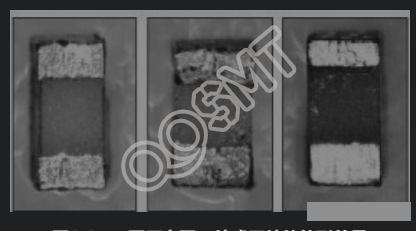
Among the performance parameters of surface mount components, the main factors that affect the mounting process are surface roughness and height dimensional errors. This effect is mainly reflected in small components, namely 0603 and 0402 chip components. Small components that appear to be exactly the same, in fact, due to differences in production quality between different manufacturers, or differences in quality control of different batches of the same manufacturer, will cause differences in the actual component dimensions and surface roughness, which not only affects the welding performance of the components, but also affects the component's welding performance. Will affect placement performance. The picture below is an enlarged outline view of the same packaged chip component produced by three manufacturers.
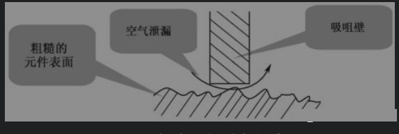
Surface roughness affects the suction force of the nozzle's vacuum system on components. In severe cases, it may cause pickup failure or material throwing, as shown in the figure below.
For patch heads that do not have soft landing technology, dimensional errors in component height may cause pickup failure or damage to components, thus affecting production efficiency and product quality. Relevant technical details will be further discussed in later chapters.
3. Detection and adjustment
When machine mounting, after picking up the components, the placement machine needs to determine two issues before mounting:
The first question is whether the center of the component is consistent with the center of the placement head. This is because when the nozzle picks up components, due to errors in the position of the component in the package and the position of the placement head, it cannot be guaranteed that the nozzle will pick up the center of the component. Therefore, position adjustment must be performed before placement to ensure that the center line of the component center and the position of the placement head are accurately aligned.
The second question is whether the component meets the placement requirements. The components provided by the supplier cannot guarantee that they fully meet the assembly requirements. At the same time, the components may cause accidental damage during transportation, storage, loading and suction. Therefore, in highly automated placement machines, it is necessary to use a placement machine. The system's vision detects whether the "assembly performance" of components is qualified.
The mechanical alignment method of early placement machines is no longer used due to speed limitations and components being easily damaged due to mechanical force. The currently widely used detection methods are optical systems, commonly known as vision systems and laser systems.
1. Visual alignment system
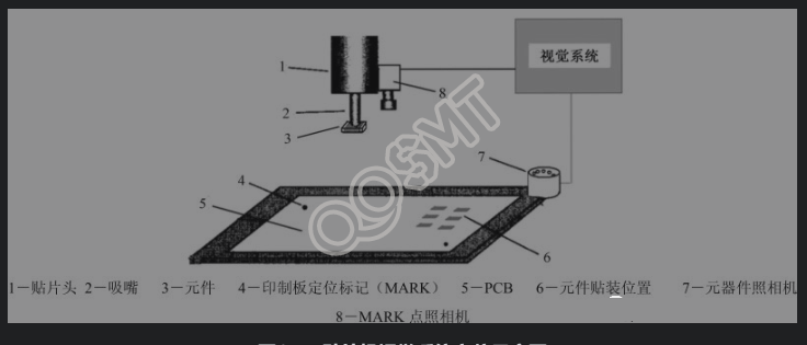
The positioning diagram of the placement machine vision system is shown in the figure below. When a new PCB to be mounted is transferred to the designated position through the board feeding mechanism and fixed, the reference (MARK point) camera CCD3 installed on the placement head searches for the MARK point in the corresponding area through the image recognition algorithm, and the system software Calculate its coordinates in the coordinate system, and at the same time send the position data where the corresponding components should be mounted to the main control computer. When the corresponding mounted component is picked up and passes through the component camera, the camera detects the component, obtains its position coordinates after picking up, and sends them to the main control computer. Compared with the target position, the position and the position where the placement head should move are obtained. Corner, adjust the position and corner before placement to achieve visual alignment.
2. Laser detection and alignment
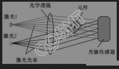
Laser inspection refers to producing a moderate beam from a light source and shining it on the component to measure the impact of the projection on the component. This method can measure the size and shape of components as well as deviations from the central axis of the nozzle.
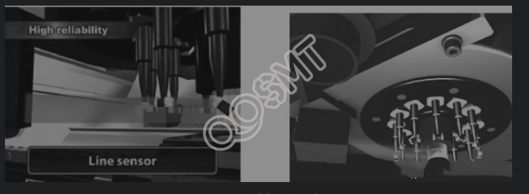
The biggest advantage of laser inspection is its speed because the components do not need to pass over the camera. However, its main drawback is that it cannot conduct pin inspection on components, so it is mainly used for detecting chip components. When laser alignment technology was introduced in the 1990s, it could only process components of 7mm × 7mm. Currently, the size of components processed by the second-generation laser alignment system has increased to 18mm × 18mm. It can recognize more shapes and the accuracy has also been significantly improved, as shown below. shown.
3. Comparison of two counterpoint systems
Camera-based optical systems and laser positioning systems that utilize laser characteristics have their own characteristics, so there are differences in use.
Laser alignment allows "on-the-fly" corrections, has the ability to handle components of all shapes and sizes, and can accurately determine component position and orientation. However, even the most sophisticated laser systems cannot measure pins and pin spacing.
The vision system can not only determine the position and direction of components, but also measure the leads and lead spacing. Therefore, most placement machines use visual positioning systems. In addition, the vision system can adapt to various updated component packages without adjusting the system, so it has better flexibility.
4. On-the-Fly technology
Flying alignment technology is a way to quickly align components in placement machines. In the early days of alignment, the detection sensor (camera or other photosensitive component) was fixed on the base of the placement machine. After picking up the component, the placement head needed to pass the detection sensor and stay for a certain period of time to complete the alignment requirements for detection and adjustment. This alignment method affects the improvement of placement speed and is replaced by a new fast alignment method, which is flying alignment technology. The so-called flying alignment refers to the method of installing the laser detection system or camera directly on the placement head, and completing the detection and centering of the components while the placement head picks up the components and moves them to the designated position. This technology is generally used in rotating multi-nozzle placement heads. It can greatly shorten the alignment time and improve placement efficiency, as shown in the figure below.
Since the flying centering technology completes the detection and adjustment work during the rapid movement of the placement head, in addition to the fast laser detection method, if a visual system is used, the speed of the CCD, A/D converter, transmission circuit and communication protocol, video The processor and memory, the operation and processing speed of the main control computer, and the electromechanical transmission servo drive system of the placement head all have corresponding speed requirements in order to achieve the purpose of shortening the alignment time and improving placement efficiency.
4. Component placement
Component placement is to accurately place the detected and aligned components into the designed position on the printed circuit board. The "accurate placement" mentioned here has two meanings. One is to accurately place the component leads on the corresponding graphics on the circuit board; the other is to accurately control the Z-axis height to ensure that the component leads are properly pressed into the solder paste, that is, The so-called placement force control. The former has actually been determined during the inspection and adjustment step, while the latter is the key to ensuring quality during placement.
Placement uses the same tools as picking components, but works in reverse to the picking process. The degree to which component leads are pressed into the solder paste, control of the Z-axis movement of the nozzle, and error-free placement are the keys to placement technology.
1. The impact of component press-in status on placement quality
Component placement is accomplished by lowering the suction nozzle in the Z-axis direction and removing the negative pressure in the suction nozzle when the component contacts the solder paste, so that the component adheres to the solder paste to complete the placement process. Correct mounting should allow the component to be properly pressed into the solder paste and rely on the adhesive force of the solder paste to fix the component on the printed board. However, in actual placement, due to errors in the height of the component, the size of the printed board in the Z-axis direction, and the movement of the nozzle, there may be insufficient or excessive press-in, both of which will affect the placement quality and thus the final assembly. quality.
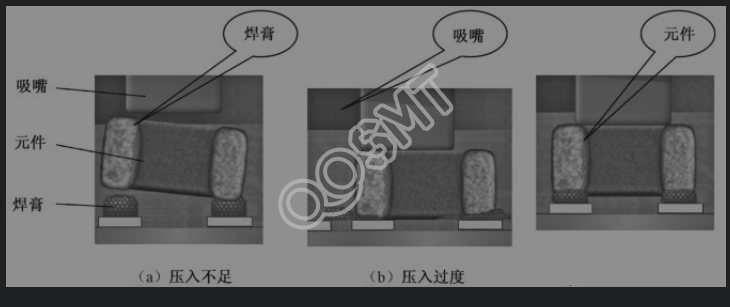
The figure below shows the different pressing degrees of component mounting. The figure (a) below shows that the component is not pressed in enough. The component cannot rely on the adhesive force of the solder paste to fix the component on the printed board. Therefore, the component may be displaced when the printed board is moved. , or a tombstone defect occurs during reflow soldering; (b) below shows that the component is pushed in too much, and the solder paste is squeezed out of the pad position. It is easy to produce bridging or welding bead defects during welding, and even damage the component due to pressure; below (c) means that the component is properly pressed into the solder paste, and good solder joints will be formed after reflow soldering in the post-process.
The above-mentioned component press-fitting degree has a greater impact on small components such as 0603, 0402 and CSP. For example, the height of 0603 components is generally between 0.15 and 0.25mm. Slight changes in the height of the circuit board may lead to unsuccessful placement of 0201 components, but these changes have no impact on the placement of larger components. Other factors, such as circuit board deformation due to reflow of components on the lower side, may also cause Z-axis height changes, which significantly affects the placement of 0603 components on the upper side of the circuit board.
In addition, the amount of solder paste for small components is very small. Due to the size error of the solder powder particles in the solder paste, excessive pressing may cause the component to skew or even crush the component.
2. Control of the Z-axis movement of the nozzle and placement force
Early placement machines did not measure the actual height of the circuit board during placement. It was assumed that the circuit boards were all flat and the thickness data of the components were consistent. On this basis, the Z-axis height during placement was calculated to control the suction. Mouth Z-axis movement. This control method is satisfactory when the mounting density is not high at that time. When the circuit board is thicker and the components are larger, the effect is satisfactory. However, with the continuous increase in mounting density and the widespread use of small components, especially the mounting of 0603 and 0402 components, it is difficult to correctly calculate the Z-axis height using this method, which usually causes failures such as insufficient or excessive press-in.
How to make the fast-moving suction nozzle accurately judge the changes in the height of the circuit board and the difference in thickness of the components so that the components can be pressed into the solder paste just right? There are many ways to solve this problem in modern placement machines.
(1) Improvement of Z-axis motion servo drive control
Early placement machines used pneumatic methods to control the Z-axis movement of the nozzle. Due to the limited accuracy of pneumatic control, it was difficult to precisely control the movement of the nozzle. Modern chip placement machines generally use servo-controlled linear motors that can accurately control errors. Coupled with the application of high-speed solenoid valves, they provide the basis for precise control of Z-axis motion.
(2) Closed-loop control of Z-axis height
Installing a height sensor on the patch head and measuring the height of the circuit board at any time can achieve closed-loop adjustment of the Z-axis height. In this way, the mounting height can be accurately controlled to the order of microns. However, this method cannot effectively adjust the pickup height problem. It can be said that it only solves half of the problem.
(3) Current monitoring control
In the nozzle Z-axis motion control design, the operating current of the Z-axis motor of the placement head is monitored. When the placement head comes into contact with the component, the operating current of the motor will increase. The advantage of this method is that it simultaneously solves the control of picking and placing. However, this method has very strict requirements on the monitoring and control circuits and mechanisms. It not only requires a certain impact force of the movement, but also requires the current monitoring device to have extremely high sensitivity, and the actuator to have extremely fast response speed, so that the system can detect When picking up, the placement head comes into contact with the component, and when the component contacts the solder paste during placement, the change in current causes the nozzle to stop in time.
(4) Mounting force sensing control
This is aAn ideal and more efficient approach, the basic idea is to perform placement force sensing on the placement head, for example, using a strain gauge to provide corresponding Z-axis height calculations for pick and place operations. The strain gauge can provide corresponding continuously changing data output according to the impact force of the suction nozzle, thereby controlling the Z-axis position of the suction nozzle in real time. When the suction nozzle picks up and places components of different heights, it automatically adjusts the placement pressure without any errors due to component height errors or Programming errors may cause damage to components. The biggest advantage of this approach is that it can improve the sensitivity and adaptability of height control. Of course, the cost of installing strain gauges on each nozzle on a rotating placement head is also considerable.
The above technologies can all realize the control of placement force and are applied in different placement machines. No technology has an absolute advantage, and products that can undergo actual production tests in the market all have technical characteristics. Theoretically, the placement force sensing control method is the ideal mode, but the corresponding technical difficulty and requirements will also increase.
5. Advanced mounting technology
Modern advanced placement machines adopt a series of advanced intelligent control technologies and gradually develop towards high speed, high flexibility and error-free placement. Speed and flexibility will be discussed in detail in later chapters. Here are just a few popular advanced placement technologies.
(1) Intelligent feeder
The settings of traditional feeders are directly related to patch programming. There is a one-to-one correspondence between which component is in which position. If the feeder is placed in the wrong position, it will lead to placement errors. Especially during the product changeover process, they require more work time to arrange the feeder location, perform feeder settings and perform patch programming.
The smart feeder records and reads feeder data through feeder programming, prints barcode labels, reads barcode data, records part numbers, batch numbers and quantities, and sets a unique "ID card" for each feeder, regardless of this The feeder can be mounted accurately no matter where it is in the material station, thereby preventing human errors, especially during the product conversion process, it shows its advantages of convenience, speed and error-free.
In addition to identifying loaded components, the smart feeder system can also:
• Track component inventory;
• Show its location on the machine;
• Show its location on the storage rack;
• Can be replaced at will during production;
• Automatic calibration function.
The intelligent feeder system with automatic scanning of feeder data is shown in the figure below.
(2) Soft landing technology
When the nozzle of the placement head picks up the component and places it on the PCB, it is usually placed in two ways. One is based on the height of the component, that is, the thickness of the component is input in advance. When the placement head drops to this height, The vacuum is released and the components are placed on the pads. Using this method sometimes causes the component to be placed too early or too late due to the excessive thickness of the component. In severe cases, it may cause component displacement or "flying chip" defects; in addition, A more advanced method is that the suction nozzle will achieve a soft landing of the placement under the action of the pressure sensor based on the reaction force generated at the moment when the component contacts the PCB, also known as the soft landing of the Z-axis, so the placement is easy and not easy. Displacement and flying chip defects occur.
(3) Intelligent placement head
Since each placement head has its own component alignment system and controller, it can perform local nozzle inspection, allowing the operator to perform nozzle position and quality inspection and diagnosis, and read out the placement without opening the machine. Head information such as production data, utilization, axial movement and rotation, and can predict required maintenance operations. Components with placement defects will be discarded and picked up again, and component error messages will be sent out to ensure the effectiveness of placement.
(4) Nozzle intelligent control device
The device includes a pneumatic monitoring and dust filter system that effectively monitors the pneumatic control system of each nozzle, checks the position of the feed belt, and ensures that small components are correctly positioned under the nozzle for reliable lifting. The dust filter in the suction nozzle prevents contamination of the gas system and ensures reliable operation of the vacuum and gas systems.
(5) Automatic correction of the placement machine
By mounting standard component test boards, using a position correction camera to test the mounting position error, and automatically collecting and updating various mounting parameters during mounting, daily maintenance and repair time can be shortened, and self-correction can be performed when the measurement results need to be adjusted.
6. Introduction to APC mounting technology
APC (Advanced Process Control) technology is an advanced assembly process control technology. Its basic idea is to consider the solder paste coating, component placement and reflow soldering process as a whole to achieve the best assembly effect.
Optimization of alignment reference in component placement is one of the APC application examples. As shown in the figure below, the traditional component placement alignment is based on the pad pattern on the printed circuit board (strictly speaking, it is based on the circuit board design circuit diagram). Since the circuit board manufacturing and solder paste application cannot be To avoid manufacturing and positioning errors, displacement errors and rotation errors will occur in the actual solder paste coating pattern and pad pattern. Through experiments, it was found that if the solder paste coating error is not considered during mounting and the pad pattern is still used as the alignment reference, the possibility of defects after reflow soldering is much greater.
Applying APC technology to use the actual solder paste coating pattern as the benchmark for component placement can prevent defects within a certain range. There are two ways to achieve this positioning.
(1) Detection and adjustment method
After the solder paste is applied, it is inspected. The solder paste printing machine with the inspection function has been used in practice. The inspection results after printing are transmitted to the placement machine, and the X of the placement point is adjusted according to the offset amount of each printed solder paste. , Y and θ coordinates can be mounted. Of course, there are still a series of practical technical problems that need to be solved in the specific implementation.
(2) Solder paste benchmark method
The basic idea of this method is to use the position of the actual solder paste coating pattern in the placement machine as the reference instead of the copper foil pattern on the printed board. This method requires applying a solder paste pattern at a position that serves as a reference point when applying solder paste, and using this pattern as a reference point for positioning the printed board in the placement machine. In the specific implementation, since the edges of the solder paste pattern are irregular and it is a three-dimensional pattern, it is more difficult to identify the solder paste pattern than the copper foil pattern. But it is obvious that this method is simple in process and has advantages in speed.