Maintenance of SMT reflow (reflow oven)
Jan 23, 2024


1. Overall maintenance plan and basic contents of reflow furnace
Regular maintenance of the reflow furnace can not only extend the service life of the machine, but also ensure stable SMT production and increase output, thereby ensuring the quality of products passing through the reflow furnace. Before performing maintenance, a periodic maintenance plan must be formulated and regular maintenance tools and supplies must be prepared.
1. Develop a maintenance plan
Maintenance is divided into daily maintenance, weekly maintenance, monthly maintenance, quarterly maintenance and annual maintenance according to the maintenance content and maintenance cycle. As shown in the table below.
2. Prepare common tools and supplies for maintenance
During the maintenance process, some items and tools are routine, while some more special tools need to be prepared separately. Here are some commonly used items and tools.
(1) Vacuum cleaner, dust-free paper or rags, brush, iron brush.
(2) Cleaning agent (CP-02), furnace cleaning agent, high temperature chain oil, WD-40 maintenance agent, kerosene, alcohol.
(3) Inch hex wrench, adjustable wrench, blade, Phillips screwdriver, slotted screwdriver, metal box, wind meter, D-TEK leak detector, multimeter, vernier caliper.
3. Basic contents of maintenance
1) Daily maintenance
(1) Use dust-free paper or rags dipped in a small amount of detergent to wipe away dust and other dirt on the surface of the reflow oven.
(2) Check the amount of high-temperature chain oil in the automatic oiler, as shown in the figure below.
(3) Open the upper cover of the furnace and clean the flux inside and the debris that fell into the furnace.
2) Weekly maintenance
(1) Select COOLDOWN mode.
(2) Adjust the furnace lift switch to raise the furnace.
(3) Use a vacuum cleaner to absorb flux and other dirt in the furnace.
(4) Use a rag or dust-free paper dipped in furnace cleaner to wipe away the flux and other dirt that the vacuum cleaner cannot remove. (5) Wipe and clean the entrance of the furnace mouth with a cloth or wiping paper.
3) Monthly maintenance
(1) Add oil to the square rod of the transmission system.
(2) Check the tightness of the transmission network.
(3) Check whether each exhaust pipe in the machine is clean and remove dirt.
(4) Use a vacuum cleaner to clean the dust inside the device and the cooling fan on the top cover.
(5) Clean the track width adjustment screw rod.
(6) Check each transmission gear on the transmission system and clean and refuel if necessary.
4) Quarterly maintenance
(1) Observe whether the top surface of the furnace and the air outlet are covered with flux and other dirt. If so, use a small shovel to shovel it off, and then use furnace cleaner to remove it.
(2) Remove the blower motor in the cold air area and remove the flux on the motor impeller and in the turbine.
(3) Check whether the front and rear steel plates of the fixed side of the track and the movable side of the track are covered with flux and other dirt. If so, use a small shovel to clean it, and then use furnace cleaner to remove it.
(4) Open the upper cover of the reflow furnace and check whether there is dirt and foreign matter on the upper hot air motor and the cooling fan on the upper cover. If there is dirt and foreign matter, remove it and use CP-02 cleaner to clean the dirt and then use WD- 40 maintenance agent to remove rust; check the lower hot air motor, if there is dirt and foreign matter, remove it and use CP-02 to clean the dirt and then use WD-40 to remove rust; check the exhaust fan for dirt, foreign matter and whether the exhaust pipe is damaged , use alcohol to clean the wall of the exhaust duct.
(5) Wipe and clean the entrance of the furnace mouth with a cloth or wiping paper.
(6) Check whether the chain is deformed and whether it matches the gear. Whether the hole between the chain and the chain is blocked by foreign matter. If so, use an iron brush to remove it.
(7) Check the parallelism of the front, middle and rear rails to see if there is any deformation. Use the PCB to run on the rails, and then check whether the gap between the rails and the PCB is too large.
(8) Check whether the UPS is in good working condition and measure its input/output voltage with a multimeter.
5) Annual maintenance
On the basis of quarterly maintenance, further maintenance is carried out on the internal and external components of the reflow furnace.
2. Maintenance of transmission mechanism
1. Accuracy correction and adjustment of the conveyor mechanism
1) Track parallelism adjustment
(1) Adjustment method: Use a vernier caliper to measure the PCB production substrate. Generally, the width of the inlet is used as the reference point. If the width of the outlet is asymmetrical, use a fixed pliers and a 19mm open-end wrench to separate the chain from the rotating gear rod at the rear end of the track and loosen it. , and then turn the rear end transmission gear rod by hand to adjust it to the same distance as the front and middle ends.
(2) The operating standards for the adjustment process are as follows.
① The entrance, central transmission combination and plate exit are the key points for measurement.
② Using the fixed side rail as a benchmark, measure the distances from Zone 3, Zone 6, Zone 9 and Zone 12 to the edge of the machine base. Each distance value must be parallel and consistent (the allowable deviation range is within ±1mm).
③ The gap distance after placing the PCB at the entrance and exit should be within 1.2mm.
④ The intermediate transmission combination should be 1~1.5mm wider than the entrance and exit.
⑤ After the basic adjustment is completed, the reflow furnace can be heated to the production set temperature, the furnace cover can be opened in real time, and the production PCB board can be used for comparison and measurement to observe whether the PCB board can slide smoothly without jamming or falling off.
2) Adjustment of track moving device
(1) Adjustment method: In the WAKE UP temperature setting, manually adjust the track width to the limit, observe the movement of the rolling pulley, and check whether it affects the track width due to resistance. If the resistance is large, the moving device should be relaxed appropriately.
(2) Operation standards for the adjustment process: The sliding condition of the rolling pulley is normal.
3) Adjustment of the front and rear steel plates on the fixed side and moving side of the track
(1) Adjustment method: First use a level to check the parallelism of the front and rear steel plates on the fixed side and moving side of the track, and then use an Allen wrench to check the tightness of the screws.
(2) The operating standards for the adjustment process are as follows.
① The front and rear steel plates should not be offset or deformed.
②Tighten the track fixing screws.
4) Adjustment of track width adjustment device
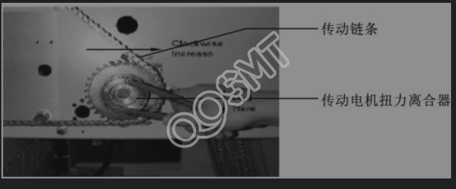
(1) Adjustment method The track width adjustment device is as shown in the figure below. Check whether the width adjustment transmission motor, transmission rod and each gear chain can operate or rotate normally. If looseness or offset occurs, use an Allen wrench and wide-nose pliers to make adjustments. If the width adjustment device is deformed or bent, it must be replaced with a new one in time.
(2) The operating standards for the adjustment process are as follows.
① The gears and chains have moderate tightness, and the device can rotate normally. Use an Allen wrench to tighten the hexagonal screws that fix the axis.
② With the shaft sleeve in the normal position, use wide-nose pliers to adjust it until there is no groove gap. The shaft transmission is normal and there should be no deviation, bending or deformation.
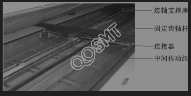
5) Adjustment of front and middle transmission devices
(1) Adjustment method: The front and middle transmission devices are as shown in the figure below. Check the engagement of the front and middle fixed racks, gears and orbital motion shafts to see if each device can operate normally. Then tighten the screws with an Allen wrench. If there is looseness or offset, use an internal hex wrench and wide-nose pliers to adjust it. If the device is deformed, bent or even broken, it should be replaced with a new one in time.
(2) The operating standards for the adjustment process are as follows.
① The front and middle fixed racks and gears must mesh with the rotating gears normally, and no deviation, bending or deformation is allowed.
② The front and middle track motion shafts need to move synchronously with the motion motor, and the movement must be smooth. Use an Allen wrench to tighten the fixed Allen screws connected between the shaft and the shaft. The shaft must not be deflected, bent, deformed, or have screws loose or broken.
2. Cleaning and maintenance of transmission mechanism
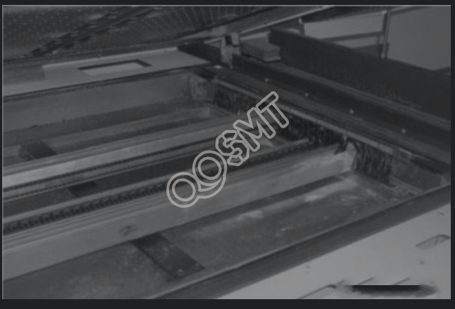
(1) The conveyor mechanism of the furnace cavity is as shown in the figure below. Clean the useless screws and residual debris in the conveyor mechanism.
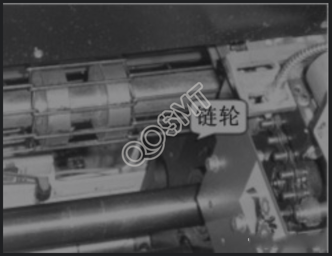
(2) The sprocket is as shown in the picture below. Clean the sprocket and add an appropriate amount of engine oil.
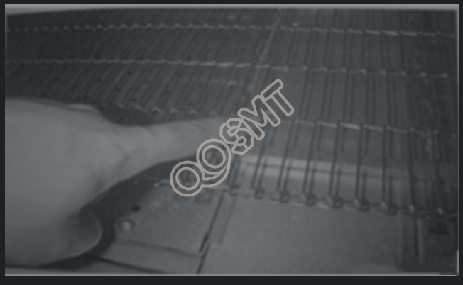
(3) Adjust the track to the widest position, find the chain net joint at the entrance, and use needle-nose pliers to disassemble the chain net, as shown in the figure below. After spraying furnace cleaner to dilute flux and other dirt on the iron plate under the net, use a shovel to remove the dirt. Finally, use a wiping paper or rag dipped in a small amount of furnace cleaner to wipe it clean.
(4) Check whether the hole between the chain and the chain is blocked by foreign matter. If so, use an iron brush to remove it.
(5) Spray furnace cleaner on the inlet, outlet and middle part of the reflow furnace, the square shaft, support auxiliary rod and width adjustment screw to dilute the flux and dirt, and use a wiping paper or rag with a small amount of furnace cleaner to clean it. It is wiped clean, and finally a layer of high-temperature oil is evenly applied to the surface to lubricate and protect it.
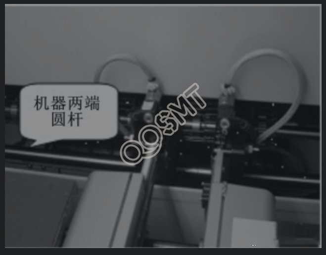
(6) The round rods at both ends of the transmission mechanism are as shown in the figure below. Use isopropyl alcohol to clean the round rods at both ends of the transmission mechanism and add an appropriate amount of engine oil.
(7) Use a rag dipped in alcohol to clean other dirt on the conveyor belt and rollers.
(8) Clean the mesh belt to drive each rotating shaft.
(9) Remove all excess lubricating oil and engine oil.
3. Maintenance of heating system, cooling and flux recovery mechanism
1. Maintenance methods of heating system
(1) The appearance of the furnace is shown in the picture below. Clean the outside of the furnace, the exhaust hood and other surrounding locations, and wipe it with alcohol if necessary.
(2) Open the upper cover of the reflow furnace and wait for the temperature in the furnace to drop to about room temperature.
(3) Check whether there is flux and other dirt on the upper cover of the furnace. If there is, spray the furnace cleaner first to dilute the flux, then use a shovel to remove the dirt, and finally use dust-free paper or rags dipped in a small amount of furnace cleaner. Wipe it clean as shown in the picture below.
(4) The inside of the furnace is as shown in the figure below. Use dust-free paper, vacuum cleaner and other cleaning tools to wipe and remove the dust and flux in the furnace.
(5) The upper and lower blower heating motors are as shown in the figure below. Check whether the motor can rotate normally, whether there is any abnormal noise, and whether it needs repair or replacement. Wipe it clean with a lint-free paper or similar cleaning tool dampened with a small amount of furnace cleaner.
2. Maintenance methods of flux recovery mechanism and cooling system
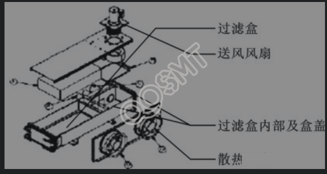
The flux filter structure is shown in the figure below.
The maintenance method of the flux filter structure is as follows.
(1) Open the flux filter box (F/FBOX), take out the filter, and replace it with a new one.
(2) Clean the surrounding components. In order to completely extract the flux during exhaust after maintenance, pay attention to the air tightness and switch contact conditions during restoration.
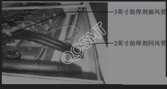
(3) The flux exhaust duct and return air duct are as shown in the figure below. Put down the hole plate, probe into the 2-inch return air duct hole with a wire with a square diameter of about 5.5mm or more, and test whether the pipe is smooth.
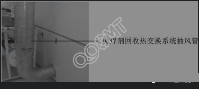
(4) Check the exhaust pipe of the flux recovery heat exchange system, as shown in the figure below. Check whether it is damaged, remove dirt and foreign objects in the exhaust pipe, open the exhaust measuring port, and use an exhaust measuring instrument to measure whether the air volume is sufficient according to the wind direction. The air volume is required to be between 500 and 700 SCFM or the wind speed is within the range of 1480 to 2470ft/min. .
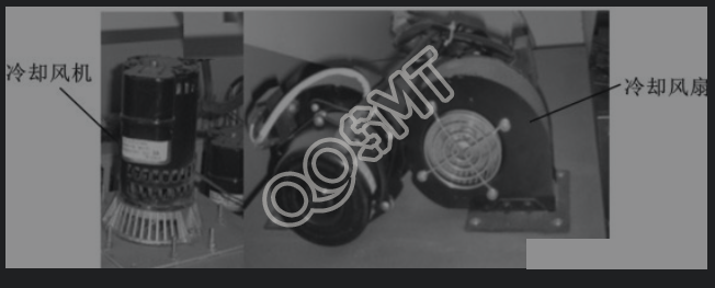
(5) Check whether the cooling fan and cooling fan can operate normally, as shown in the figure below, wipe off dust and dirt in time, and use a vacuum cleaner to absorb fine dust.
4. Maintenance of reflow oven electrical appliances and computer systems
1. Maintenance of electrical system
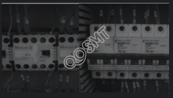
The circuit connections and component operation in the electrical system of the reflow furnace should be checked regularly to ensure that there is no circuit breakage or leakage, and that the relays and air switches are working properly. The relay and air switch in the reflow oven are shown in the figure below.
(1) Tighten the screws of each circuit connector with an inner hexagon or screwdriver. Observe whether the insulating rubber of each line is damaged or yellowed and aged. If necessary, replace it or wrap it with insulating tape.
(2) If the relay is damaged, the relay needs to be replaced. The specific replacement method is as follows.
① Turn off the power, open the electrical control box panel, and check to find the damaged relay components.
② Use a screwdriver to unscrew the fixing screw of the relay, disconnect the circuit, remove it, and apply heat dissipation agent on the back of the new component and the corresponding heat dissipation aluminum plate.
③ Install and fix the new relay, connect the wiring, check to make sure it is correct, and then turn on the power for testing.
(3) If the air switch trips, turn off the power immediately and check to confirm the cause of the trip. After the fault is eliminated, open the electric control box, reset the tripped air switch, and finally turn on the power to test the working condition.
2. Computer system maintenance
Computer system maintenance is an important measure to improve computer usage efficiency and extend computer service life. When using a computer system on a daily basis, it is necessary to avoid moisture, impact, etc., prevent mobile storage devices from unknown sources from being connected to the system, and keep the computer surface clean and well dissipated.
When maintaining computer hardware systems, you should mainly pay attention to the following points.
(1) Ensure reliable connection between power cord and signal line.
(2) When turning on the computer, power on the external devices first, and then power on the host; when shutting down, power off the host first, and then all external devices. Do not turn off the computer immediately after turning it on, and do not turn it on immediately after turning it off. There should be an interval of more than 10 seconds in between.
(3) When operating the keyboard, do not press the keys too hard, otherwise the service life of the keyboard will be affected.
(4) Clean the dust frequently and wipe the surface of the keyboard and chassis. Cover the computer with a dust cover when not in use.
(5) Do not move the host while the power is on.