SMT solder paste printing machine operation reasons and inspection introduction
Jan 23, 2024


Preface
Solder paste printing is the first step in the SMT process and is a key step to ensure SMT quality. It directly affects the welding quality and reliability of surface assembly components. At present, the most widely used process is the metal mesh solder paste process of the fully automatic printing machine. The fully automatic solder paste printing machine mainly consists of the main body of the equipment, PCB transmission mechanism, scraper device, printing (work) table, optical vision system, computer control system, power It is composed of a driving device, an off-grid mechanism and a screen cleaning mechanism. The basic working principle of the solder paste printing machine is that after the PCB is fed into the solder paste printing machine from the conveyor belt, the clamping device fixes it on the X-Y-θ platform. (Multiple) mark identifies the coordinate value deviation of the point and corrects the deviation. The drive motor adjusts the X-Y-θ platform and moves the PCB in the three directions of X-Y-θ to accurately align the PCB with the stencil. Finally, the solder paste is printed on the PCB pad through the special opening of the stencil.
1. Understanding of solder paste printing machines
Solder paste printing refers to printing solder paste evenly on the pads of the PCB to ensure that the chip components and the corresponding pads can be firmly combined. Solder paste printing machines can be divided into three types: fully automatic, semi-automatic and manual. Among them, the fully automatic printing machine has a high degree of automation and can be connected with other SMT equipment, and is suitable for large and medium-volume production; the semi-automatic printing machine cannot be connected with other SMT equipment, but uses manual transmission, manual positioning, and automatic printing, and is suitable for medium- and large-scale production. , small batch production; the manual printing machine has a simple structure and is cheap. The loading, positioning, and printing are all manual, and it is suitable for use in scientific research institutes and teaching. The solder paste printing machines currently configured in the SMT production line are all fully automatic printing machines. The fully automatic solder paste printing machines have comprehensive functions and can automatically complete a series of solder paste printing operations.
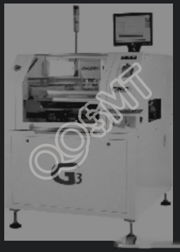
The fully automatic solder paste printing machine mainly includes: mechanical system, optical vision system, PCB positioning system, air path control system, computer control system, automatic cleaning system, etc. With the development of the SMT industry, in order to adapt to the requirements of fine-pitch, high-density electronic packaging technologies such as QFP, SOP, BGA, CSP, 0603, 01005, etc., the new generation of fully automatic visual printing machines produced in my country are synchronized with international leading technologies. The equipment has a high-resolution vision processing system, high-precision transmission system, suspended adaptive scraper, precise plate positioning processing and smart screen frame clamping structure. Its compact structure combines accuracy and high flexibility. , providing the features needed for efficient, precise printing. The G3 produced by GKG is a fully automatic visual printing machine with high precision and high stability. Taking GKG's G3 printing machine as an example, we will introduce the structure of a fully automatic solder paste printing machine. Its appearance is shown in the figure below. .
1) Mechanical system of solder paste printing machine
The mechanical system of the solder paste printing machine mainly consists of a transmission mechanism, a printing workbench, a scraper mechanism, an off-grid mechanism, a screen clamping mechanism and an automatic cleaning mechanism.
(1) Transmission track device.
The transmission mechanism adopts motor drive, pulley transmission and automatic adjustment of guide rail width, as shown in the figure below. In actual operation, the substrate is first sent to the printing workbench from the incoming track to print the solder paste. After printing, it is sent out from the outgoing track. In order to control the order of substrate transfer, waiting sensors are installed on the incoming and outgoing tracks respectively. When the substrate passes through the track, the incident light beam of the photoelectric sensor is blocked or reflected, thereby detecting the presence of the substrate, and controlling the positioning of the substrate on the track through the cylinder-type substrate stopper.
(2) Smart stencil clamping structure.
As shown in the figure below, the highly adaptable screen frame clamping system can print screen frames of various sizes and can quickly change machine models during the production process.
(3) Accurate platform alignment.
The X-Y-θ drive mechanism realizes movement in the three directions of X-Y-θ for platform positioning. The driving mechanisms of X-Y-θ are all servo motors, which are used to ensure calibration accuracy, as shown in the figure below.
(4) Scraper head and driving mechanism.
The print head is driven by a suspended self-adjusting stepper motor. It is designed based on the difference in pressure required by the front and rear scrapers and the stability of the lift. The clamping design is also designed to prevent solder paste from leaking and the blade to have a certain elasticity. The pressure of the scraper, lifting speed, printing speed, printing range, etc. can all be set using the software. At the same time, it provides a variety of demoulding methods to adapt to PCB boards with different tin placing requirements, and provides a good printing control platform. The print head is shown in Figure 1 below, and the suspended adaptive scraper is shown in Figure 2 below.
Figure 1 Print head
Figure 2 Suspended adaptive scraper
2) Optical vision system
The precise optical vision system is shown below. This system achieves accurate mark point identification of PCB/stencil by using light sources such as ring light/coaxial light, a unique optical path system and all-round light source compensation. The X and Y directions of the CCD use high-precision servo motors, combined with high-precision ball screws, to jointly ensure the accuracy of image acquisition, thereby ensuring the accuracy of the machine.
3) PCB positioning system
The stable and reliable PCB positioning system is shown in the figure below, including round belt PCB transfer guide rails, original PCB board pressing and elastic side pressing devices, coupled with bottom vacuum nozzles and magnetic ejector pins to ensure that the PCB board is stable, reliable and stable after positioning. The flat surface of the board completely solves the problem of difficult positioning of special-shaped boards such as double-sided boards, deformed boards and thin boards below 0.6mm by fully automatic printing machines.
4) Electrical separate control system
The electrically separated control structure for easy maintenance is shown in the figure below. The printing press requires not only electric drive but also pneumatic drive. When the printing press is working, various electrical appliances and motors need to be driven by power supply voltage; while mechanisms such as scraper drive, substrate clamping and screen clamping, and workbench pallet lifting and lowering need to be driven by air pressure. By using an electrically separated control structure, the electrical control part, pneumatic control part, industrial control part and conversion card of the printing press are concentrated at the front and rear doors. This structure not only saves space, but is also simple, safe and easy to maintain.
5) Screen cleaning system
The automatic and effective stencil cleaning system has three cleaning methods: dry, wet and vacuum. The structure shown in Figure 2-10 has an automatic and effective screen cleaning function, and the computer can be used to set the cleaning cycle, time, speed and other parameters to remove residual solder paste in the mesh to ensure printing quality.
6) Computer control system
The computer control interface is shown in the figure below. The operator uses it to understand the status of the printing press, perform file management and all machine operations. The mouse is used to move the cursor on the screen, and each button on the mouse (SELECT, NEXT, EXIT) is used to set parameters and operate the printing press.
2. Preparation before operation of solder paste printing machine
Preparations must be made before solder paste printing. Process and technical personnel should do the following:
① Familiar with the process requirements of the product;
②According to the product’s process documents, receive the inspected and qualified PCB;
③Choose the correct solder paste material, printing machine, stencil, scraper, etc.;
④ Determine reliable processes, such as good positioning, cleaning and wiping, etc.;
⑤ Create visual images of mark points, etc.
And we should optimize and select the best design solution while deeply understanding the product structure and process characteristics. For different products, set corresponding printing parameters in the printing program, such as working temperature, scraper pressure and speed, automatic cleaning cycle of the stencil, etc. At the same time, strict process management and process regulations must be formulated to ensure solder paste printing Finished well and smoothly.
1. Process analysis and plan formulation
1) Develop process regulations for solder paste printing
In order to achieve good printing results, operators should fully understand the process characteristics of the product structure based on the inspection technical requirements of the electronic products to be processed and the finished products, and formulate the optimal plan to ensure the smooth completion of the printing work. For small batches and multiple varieties of products to be processed, semi-automatic production lines with semi-automatic printing machines can be used. When solder paste printing in a fully automatic, large-scale production line may cause a bottleneck that affects production efficiency, a semi-automatic printing machine can be configured next to the fully automatic production line to improve production efficiency. The principles, printing processes, and operating principles of semi-automatic printing machines and fully-automatic printing machines are basically the same. The difference is that the PCB clamping process of semi-automatic printing machines is placed manually.
Make sure to make preparations before operation, and refer to the following aspects to formulate the process regulations for solder paste printing.
(1) Follow the principles of solder paste selection and use and store solder paste correctly. During the production process, the solder paste printing quality must be 100% inspected, that is, whether the solder paste pattern is complete, whether the thickness is uniform, and whether there is any phenomenon such as solder paste sharpening.
(2) Set the printing programming parameters, and set the scraper pressure, scraper speed, scraper angle, off-grid speed, stencil cleaning mode and cleaning cycle according to the process requirements, as well as stencil and PCB mark perspective image production, etc.
(3) Adjust printing condition settings, confirm the printing effect through trial printing, and check and correct relevant parameters to achieve the best results.
2) Develop solder paste printing process management process
The success of solder paste printing depends on three key elements in the printing process: solder paste rolling, filling, and demolding. The printing effect of PCB directly affects the quality of the product. In actual production, about 60% of the PCBs that fail to pass inspection and need to be reworked are due to poor solder paste printing. Therefore, accurate control of solder paste, scraper, and stencil is the key to ensuring stable printing quality.
Develop various work instructions based on process requirements and types of solder paste and printing machines. Such as solder paste storage and use instructions, ×× printing machine operation instructions, solder paste automatic printing process instructions, inspection instructions, etc. Strictly standardize the operation process to ensure the quality of solder paste printing.
2. Process preparation for solder paste printing
1) Process flow The process flow of solder paste printing is shown in the figure below.
2) Preparation before operation
(1) Equipment status check. All switches of the equipment must be turned off before printing; turn on the power of the air compressor, discharge the accumulated water before starting the machine, open all air valves, and confirm that the air pressure value of each part meets the requirements of the printing machine; check whether there is accumulated water in the air filter, If there is any, discharge it; install the wiping paper and check the amount of alcohol in the screen cleaner container. If it is less than 1/3 of the total capacity, add it; check whether the mechanical parts of the machine are normal and whether they affect the normal operation of the machine. The running components are placed in the machine. If any problems are found, they should be dealt with in time until the problems are solved.
(2) Check the screen plate and scraper. The screen should be intact and the leakage screen should be complete and not blocked; the scraper blade and screen should be clean, and brushes, cleaning agents, rags, etc. for cleaning should be prepared.
(3) Prepare solder paste. Select solder paste according to the provisions of the product process documents, and check whether the solder paste or red (yellow) glue is ready to be warmed up. The container lid can only be opened after it has been completely warmed up. Before printing, use a stainless steel stirring rod to fully stir the solder paste in one direction before use.
3) Power on operation
(1) Make sure there are no foreign objects inside the machine before you can turn it on.
(2) Open the air valve of the air supply pipe and ensure that the air pressure meets the requirements of the printing machine.
(3) Turn on the power switch of the printing press.
(4) Press the green "MACHINE ON" switch on the control panel on the front of the machine, then the "MACHINEON" light on the control panel will light up. The machine starts to initialize and enters the main interface.
4) Install the screen and scraper
(1) Install the screen plate first, and then install the scraper.
(2) When installing the stencil, insert the stencil into the stencil track, push it into place and clamp it tightly.
(3) When installing the scraper, distinguish between the front and rear scrapers. Install the rear scraper first, then the front scraper, as shown in the figure below.
5) Process operation principle
The PCB is fed into the solder paste printing machine along the conveyor belt, and the machine automatically finds the main edges of the PCB and positions them. The Z-shaped frame moves up to the position of the vacuum plate, applies vacuum, and then securely holds the PCB in a specific position. After the visual axis (lens) slowly moves to the first target mark (reference point) of the PCB, the machine can move the stencil to align it with the PCB, and the machine can move the stencil in the X and Y axis directions and in the θ axis. direction of rotation, as shown in Figure 1 below. Once the stencil and PCB are aligned, the Z-shaped frame will move upward, driving the PCB to contact the underside of the stencil, as shown in Figure 2 below.
Figure 1 PCB positioning
Figure 2 Z-shaped frame moves upward
When moved into place, the scraper will push the solder paste to roll on the stencil and print on the PAD position of the PCB through the holes in the stencil. The solder paste fills the holes in the stencil and accumulates on the PCB, as shown in the figure below. After printing is completed, the Z-shaped frame moves downward to separate the PCB from the stencil (i.e. demoulding). At this time, the machine will perform 2D and 3D automatic optical inspection (check solder paste coverage) at an interval of 21 points per second (at least 0.0012 inches). After the PCB passes the conventional inspection, the machine will send the PCB out to the next process. The printer will then ask the next PCB to be printed to go through the same process, just printing in the opposite direction with a second squeegee. After the PCB is sent out, the machine will automatically clean the screen to ensure printing quality.
When the scraper moves forward at a certain speed and angle, it will exert a certain pressure on the solder paste, thereby injecting the solder paste into the mesh (i.e., the opening of the mesh). The viscous friction of the solder paste causes the solder paste to move between the scraper and the mesh. Shear force is generated at the junction of the boards, and the solder paste is smoothly injected into the mesh. The degree to which the solder paste fills the stencil opening depends on the amount of solder paste; the completeness of the demoulding depends on the amount of solder paste leakage and the integrity of the solder paste pattern; the completeness of the demoulding also determines the success of solder paste printing. . Since solder paste printing is a key process to ensure the quality of SMT assembly, the quality of solder paste printing must be strictly controlled.
3. Inspection and maintenance before operation of solder paste printing machine
1. Inspection of electrical and gas systems
The inspection items of the electrical and gas systems are confirmed by the operator, and the methods are shown in the table below.
2. Inspection work of the conveyor system
The inspection work items and confirmation methods of the conveyor system are shown in the table below.
3. Inspection of printing workbench
The inspection work items and confirmation methods of the printing workbench are shown in the table below.
4. Inspection work of vision system
The inspection work items and confirmation methods of the vision system are shown in the table below.
5. Scraper inspection operation
The scraper inspection work items and confirmation methods are shown in the table below.
6. Inspection of cleaning system
The cleaning system inspection work items and confirmation methods are shown in the table below.
7. Inspection of safety protection system
The inspection work items and confirmation methods of the safety protection system are shown in the table below.