Introduction to DEK solder paste printing machine level and height calibration methods and methods to improve solvent jet failure
Jan 24, 2024

Today I will share two parts of the DEK solder paste printing machine:
1. DEK solder paste printing machine level and height calibration operation method
2. DEK solder paste printing machine wiping mechanism modification plan
1. Operation method for level and height correction of DEK solder paste printing machine
1. Preparation
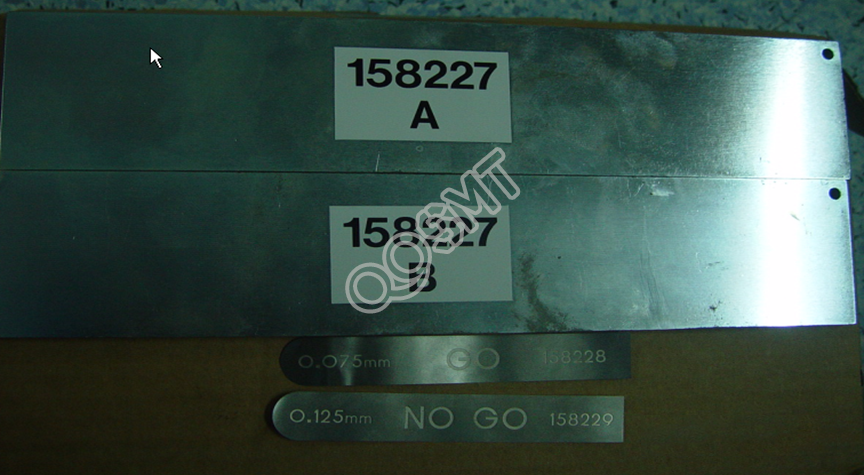
Prepare the jig (two iron plates and two thin gauges), as shown in the figure below:
2. Track level and height correction
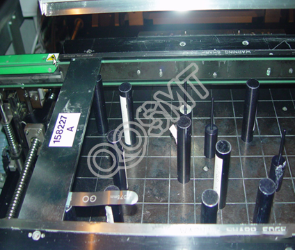
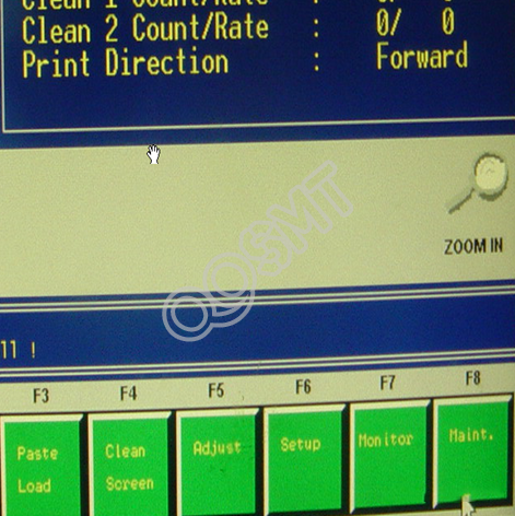
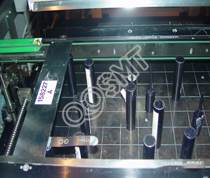
• First select the 265test program, place the jig on both sides of the track, as close to the sides as possible (but clamp it as shown in Figure 1 below). Then select F8 (maint) on the main screen to enter the interface in Figure 2 below.
Figure 1 Calibration fixtures are placed on both sides of the track
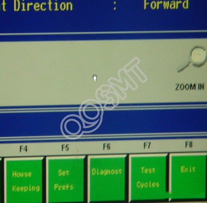
Figure 2 Maint main interface
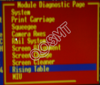
• Select F6 (Diaghost) here to enter the interface shown below
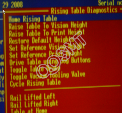
• Select RisingTable here to perform the lifting operation of the Main Table, as shown in the figure below
• Select HomeRising Table, return the Main Table to zero, and then select Raise Table To Vision Height. At this time, the Main Table will rise to the image height. At this time, the Surport Pin will push against the PCB, where the level of the track and the height of the top board will be corrected. (The operation interface is as shown below)
• Push the Pin under the fixture and check the distance between the Pin and the fixture. Use a thin gauge to measure it. Normally, 0.075 can be inserted but 0.125 cannot be inserted. Otherwise, adjust the screws holding the track until the requirements are met (four angles are consistent). As shown below
• Due to the adjustment of the height screw, the height of the screen will change. Here you need to correct the height of the screen. In the Table lifting operation, raise the Table to the printing height in order from low to high, and then press the Set Reference Print Heigh option. It will A pop-up shows the height of the current Table, as shown in the figure below. Now check whether the height of the Table meets the requirements. If it does not meet the requirements, adjust the value, and then click the Move option in the picture. The Table will move to the height of the value we specified until it reaches the height we require. Then select the set height option in the picture. The current height is the new printing height.
• Finally, lower the Table height in order from high to low until it returns to zero. This completes the entire calibration process
2. Methods to improve DEK solvent spray failure
DEK's original solvent spray mechanism often blocks the holes, causing the stencil to be unclean, resulting in the problem of less tin in printing. In this case, we conducted a detailed analysis and made a series of improvements, which we now share with you. !
Reduce wear and tear on DEK solvent spray mechanism
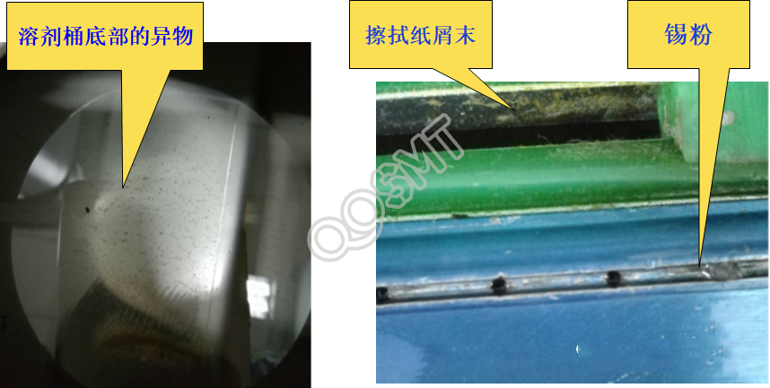
1. Analysis of the reasons for blockage of DEK solvent injection mechanism: (as shown in the figure below)
There is foreign matter in the solvent barrel.
After vacuum wiping, wipe off the paper dust.
Tin powder is adsorbed on the nozzle.
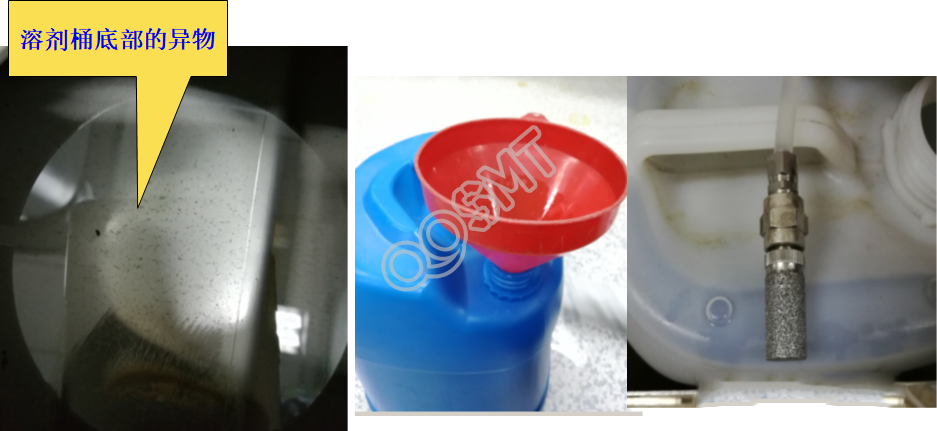
1) Improved analysis of foreign matter in solvent barrels:
The particles are very small and are mainly mixed into the bucket from around the lid of the solvent bucket when adding solvent, as shown below.
Improvement: a. Use a funnel to add solvent.
b. Add a filter to the outlet of the solvent barrel.
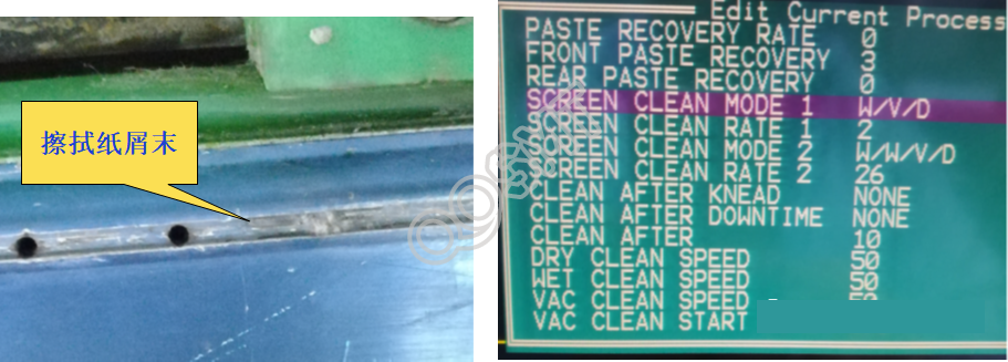
2) After vacuum wiping, wiping paper scraps will not improve:
The current wiping mode is W/V/D, which is an integrated mode. Wiping paper scraps will fall off the wiping nozzle, as shown in the figure below. Based on this situation, re-evaluate the wiping paper and use better wiping paper to reduce and avoid This problem.
3) Improvement of tin powder adsorption on nozzle:
Tin powder is adsorbed on the nozzle, which is currently the most common form of hole blocking. Because there is a groove between the nozzle holes, after the solvent is sprayed, the tin powder adsorbed on the nozzle head flows back along the groove into the nozzle hole. Especially after the line is stopped and the wiping mechanism stops working, the tin powder adsorbed on the nozzle will dry and harden, causing hole blocking.
Solution: Use a jig to punch through the clogged hole. As shown below.
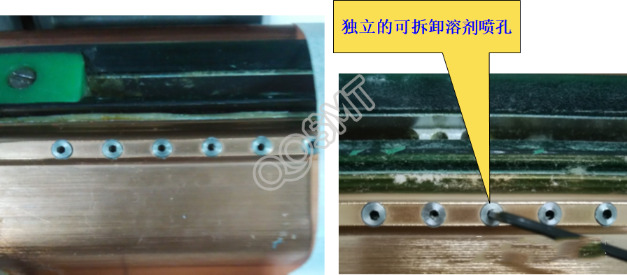
Disadvantages: The size of the fixture and the hole are inconsistent, causing the hole to become larger and the solvent to be sprayed unevenly.
4) Using the above method, the problem of clogging still cannot be completely avoided. After clogging, cleaning is very troublesome, and there will be the problem of hole enlargement as mentioned above. Therefore, we are thinking about transforming all the injection holes: changing the injection holes of the solvent injection mechanism. It is a nozzle hole that can be disassembled independently. Moreover, the nozzle holes are higher than the grooves between the nozzle holes, so it is difficult for the solvent to reversely seep into the holes and cause blockage. Even if the hole is blocked, it can be easily cleaned using ultrasonic waves. As shown below!