Introduction to the structural characteristics of SMT placement machines
Jan 25, 2024
Preface
Although there are hundreds of various placement machines on the market now, with various performances, parameters and degrees of automation, their basic function is to correctly, accurately and quickly mount components onto printed circuit boards. . Therefore, mainstream chip placement machines have some common structural characteristics. Understanding these characteristics will help to draw inferences from one example and grasp the main features of the chip placement machine, thereby comprehensively grasping the placement technology.
1. Turret structure
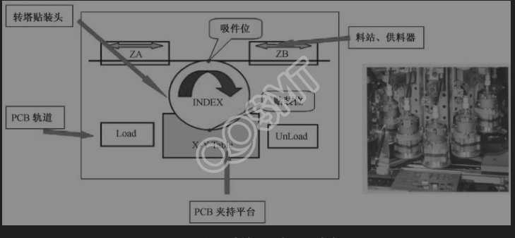
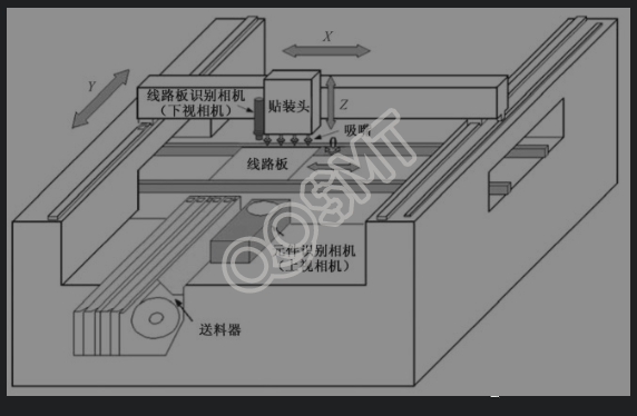
The turret structure (Turret Head) was the most commonly used structure in high-speed placement machines in the past. Since its advent in the 1980s, this structure has been the main model of high-speed placement machines for a long time. This structure usually has a fixed turret that rotates while sucking, photographing, mounting, and replacing nozzles. The component feeder is supplied by a reciprocating feeder behind the machine, and the circuit board is supplied by , Y worktable driven to achieve high-speed placement. Due to the use of cam linkage, the mechanical structure is relatively stable, and it is very efficient and fast when mounting small components. The theoretical speed of the fastest turret-type chip placement machine has reached more than 50,000 points/h. However, due to the limitations of the mechanical structure, the speed of the placement machine using this structure has reached its limit and it is difficult to increase it. The schematic diagram of the turret structure and the patch head are shown in the figure below.
1. Advantages and disadvantages of turret structure
(1) Advantages of turret structure
• Up to 6 nozzles of different sizes are suitable for any placement head on the turret, and no nozzles need to be replaced during work. In other words, any nozzle can pick up components at any time, eliminating excessive and unnecessary operating steps.
• The vision system is installed between the pick-up point and placement point of the turret-type placement machine, allowing image processing "on the fly".
• A simple mechanically geared turret design keeps power supply cables, servos, encoders, sensors and cameras stationary so there are no electrical problems that can arise due to constant bending stresses from motion breaking the lines (e.g. , a malfunction may occur when the gantry is constantly running from the feeder to the camera and circuit board).
• Nowadays, the placement speed of turret-type placement machines can reach more than 54500 points/h (such as HT122). The best single-head bench-mounted placement machine can only mount about 15,000 points/h. In order to achieve the same speed for a bench-mounted placement machine, multiple machines are required, which means that there will be more parts to maintain, lubricate, calibrate and rework.
• Use a turret design with the feeder installed on only one side of the placement machine. In this way, the front and rear width of the placement machine can be reduced by about 1 m. To this end, there is no need to install an additional feeder and component storage device on the other side of the production line, thus reducing the area of the entire operating area.
(2) Disadvantages of turret structure
• Due to the limitations of the mechanical structure, its placement speed has reached its limit and cannot be greatly improved. It also takes up too much space and makes a lot of noise.
• The turret-type SMT machine can only mount tape-packed or bulk-packaged components, but tubes and disks cannot be mounted.
• The placement head position of the turret-type placement machine is fixed relative to the PCB placement part. The PCB is accurately positioned at the specified placement position by running in the X-Y direction. Due to the vibration generated by high-speed movement, the The position of the components that have been mounted will shift, ultimately affecting the placement accuracy.
• The range of mountable components is limited to chip components and is not suitable for mounting IC devices.
(3) Limitations of turret structure
When the turret structure is in motion, the placement speed is limited due to the limited maximum allowable value of radial acceleration on the vacuum nozzle. The device on the nozzle is subject to the acceleration vector force. This vector is the resultant force of centrifugal force and tangential force. The resultant force acting on the device is balanced by the friction force between the device and the end face of the nozzle. This friction force is restricted by the suction force on the end of the nozzle and the friction coefficient between the device/nozzle.
According to mechanical motion engineering mechanics calculations, the maximum allowable acceleration between the device and the nozzle generally does not exceed 50 m/s². So when high placement throughput is required, the diameter of the turret should be reduced. Another factor that restricts the placement speed of the turret structure placement machine is: the maximum allowable acceleration of the first-placed device on the PCB, which is usually 7 to 10 m/s².
The turret time has three time determination periods: turret shift movement acceleration limit, PCB movement acceleration limit and feeder shift movement limit. Among these three time periods, the longest period is the turret structure placement output. Constraints. In addition, if the distance between the two mounting positions on the PCB exceeds 30mm, the mounting output will be reduced by 50%, and the changeover time between the two feeders will also affect the production capacity. Large-size packages and heavy devices will also reduce placement output. This is because such devices are mounted at the end of the mounting cycle after all small-size devices have been mounted.
Therefore, turret-type chip placement machines are mostly used in situations where there are many resistive and capacitive components and the assembly density is high, such as computer boards, mobile phones, home appliances and other products.
2. Turret structure features
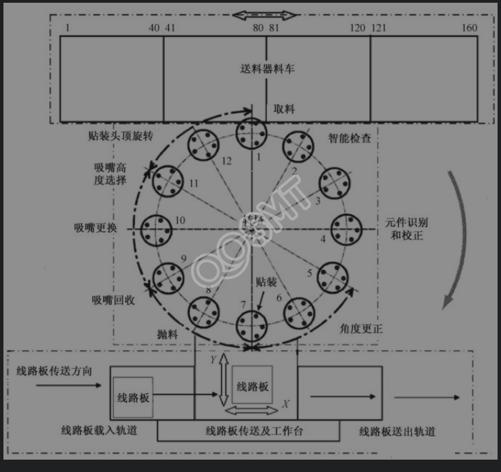
The main structure of the turret-type chip placement machine can be simply divided into the following three parts (as shown in the figure below).
(1) Circuit board transmission and workbench
The circuit board is fed into the loading rail of the machine from the upper conveyor rail, and then fed into the workbench. The workbench moves in the X and Y directions to realize the placement of components with different coordinates. After the components are mounted, the circuit board is sent from the workbench to the delivery track and the lower conveyor track. Generally, circuit boards are conveyed by belts on both the loading track and the delivery track. When entering the workbench, a pneumatic or electric push arm pushes the circuit board from the loading track to the workbench, which takes 2.5 to 4 seconds. FUJI's CP series adopts the transporting claw method. Use the transporting claw on the workbench to grab the circuit board from the loading track. After the mounting is completed, it is sent to the delivery track to ensure that the circuit board is transported The time is only 1.4s.
The workbench carries the circuit board and moves in the X and Y directions under the turret placement head according to the position set in the placement program. The X and Y worktables of rotary table placement machines are generally driven by servo motors and fully closed-loop controlled by encoder feedback.
(2) Turret for component pickup, identification, correction and placement
After the components are picked up from the feeder, they are inspected, identified, calibrated and angle corrected before being mounted on the circuit board. The components that fail to pass the identification are then thrown away, and the nozzles are replaced and pre-rotated to prepare for the next pick-up. The turret of a turret-type placement machine generally has 12 to 24 placement heads. The following takes a turret with 12 placement heads as an example to introduce the functions of the placement heads in each position.
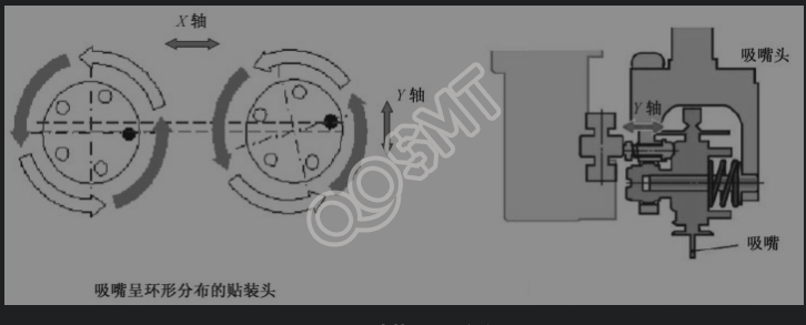
Each placement head generally has 5 to 6 suction nozzles, some of which are distributed annularly within a ring, and some are distributed radially in a star shape. The appropriate nozzle can be selected according to the needs of the component. Since the component is not necessarily in the center of the material belt, the suction nozzle is corrected based on the last corrected suction deviation when suctioning. A placement head with annular distribution of suction nozzles can compensate for slight deviations in the X and Y directions of the suction material through the rotation of the turret and the rotation of the placement head; a placement head with a star-shaped radial distribution of suction nozzles can compensate for slight deviations in the X and Y directions of the suction material through the rotation of the turret. To compensate for the X direction of the suction material, the deviation in the Y direction of the suction material is compensated through the rotation of the Y-axis cam (as shown in the figure below).
Because components vary in size and weight, the turret handles components of different sizes and weights at different speeds. For smaller components, such as 0201, 0402, 0603 and 0805, etc., the turret can generally be rotated and mounted at full speed; for larger components, such as tantalum capacitors, SOIC, PLCC and QFP, the turret needs to be rotated and mounted during all processes. Medium speed reduction. If there is a component on a placement head on the turret that needs to be slowed down, the speed of the entire turret will slow down as that component needs to be slowed down.
Components can be identified using different lights and intensities, such as front light, side light, and backlight. The components of the turret-type placement machine can only be identified once, and multi-view identification is not possible.
(3) Feeder Carriage for component supply and switching
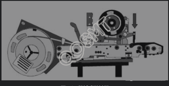
The feeder-mounted trolley reciprocates behind the machine so that the placement head can move to the 12 o'clock position to pick up the required components as the turret moves. Since the chip components are installed in a feeder truck that requires high-speed reciprocation, the components must be in a stable container, so the chip placement machine with this structure can only accept tape-packed components and boxed bulk materials. The feeders of the turret-type chip placement machine all use mechanical feeders (as shown in the figure below). When the material truck sends the required feeder to the 12 o'clock position where the chip placement head suctions material, there is a mechanical feeder behind the chip placement head. The push rod pushes the compression spring of the feeder, and the feeder feeds the material. Since the feeder of the turret-type high-speed machine is mechanical, different feeders need to be prepared according to the different widths, materials and step distances of the component tapes.
The feeder switching time of the turret-type high-speed machine is generally longer than the theoretical component placement time. For example, the theoretical placement time of Universal's 4797 series is 0.072 s, while the feeder switching time is 0.09 s. Therefore, when editing and optimizing the program, consideration should be given to reducing the switching of feeder trucks as much as possible.
2. Arch structure
The arch structure is also called the boom structure, and it can also be called the platform structure (Platform) or the overhead cantilever structure (Overhead Gantry). Now almost all multi-function placement machines and medium-speed placement machines adopt this structure.
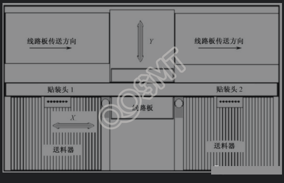
This structure generally uses an integrated base frame (Base Frame). The X and Y positioning systems of the placement head beam are installed on the base frame, and the circuit board identification camera (downward-looking camera) is installed next to the placement head. The circuit board is transferred to the working platform in the middle of the machine and fixed. The feeders are installed on both sides of the transfer track. A component identification camera is installed next to the feeder (as shown in the figure below).
(1) X, Y positioning system
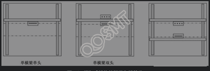
In the more economical medium-speed placement machine, the X and Y drive systems use motor screw drives and encoder feedback. Generally, multi-function placement machines and some higher-precision medium-speed placement machines are driven by motor screws and have linear grating feedback; some higher-precision placement machines are driven by linear motors and have linear grating feedback. Depending on the requirements for function and speed, different numbers of beams can be used and different numbers of placement heads can be installed (as shown in the figure below).
① Single beam and single head. The crossbeam moves along the Y-axis on the basic frame, and the placement head moves along the X-axis on the crossbeam. The identification of reference points on the circuit board and the pickup, identification, correction and placement of components are all completed by one placement head.
② Single beam and double ends. Placement heads are installed on both sides of a single beam. The front placement head picks up and places components on the front feeder, and the rear placement head picks up and places components on the rear feeder. Generally, the functions, component range and accuracy of the placement heads installed on both sides of a single beam are not exactly the same, so that the entire machine has higher flexibility and a larger component range.
③ Double beams and double ends. The basic frame of the machine is equipped with two beams, each of which is equipped with a placement head. When the circuit board enters the work platform and the front placement head is identifying the reference tape, the rear placement head can suck materials first; when the front placement head starts sucking materials, the rear placement head can place components first. The double-beam structure can also install two placement heads with different functions, giving the entire machine greater flexibility and a larger range of components.
④ Some arch-type placement machines use a crossbeam to move along the X-axis on the basic frame of the machine, and the placement head moves along the Y-axis on the crossbeam. The component recognition camera is installed on the Y beam. After each nozzle of the placement head has absorbed the component, it can be identified and corrected when it passes above the component recognition camera.
⑤ There is also an arch-structured placement machine. Its crossbeam is fixed on the basic frame of the machine. One or two placement heads move along the X direction on the crossbeam to absorb and take photos to correct the placement components. X-axis displacement occurs on the plate. After the circuit board is sent to the workbench by the conveyor board device, the workbench moves in the Y direction to control the displacement of the Y-axis of the circuit board (as shown in the figure below).
(2) Mounting head system
The traditional arch-structure placement head has a single nozzle structure and a multi-nozzle parallel structure (as shown in the figure below). The single-nozzle placement head can only place one component in one placement cycle, and its placement accuracy is relatively high. The multi-nozzle parallel placement head has 2 to 12 parallel nozzle placement axes (Spindle), which can pick up, correct and place multiple components in one placement cycle, thereby increasing the placement speed.
In a placement head with a multi-nozzle parallel structure, the distance between the nozzles is the same as the distance between the feeder tracks. When using the same feeder, multiple nozzles can be lowered to the feeder at the same time. height to simultaneously pick up materials (Gang Pick), which can increase the speed of picking up materials.
Since chip components come in different sizes and the number of mounting axes on the placement head is limited, arch-type placement machines generally have a special nozzle storage mechanism (Nozzle Stocker) for the placement head to use when needed. Perform nozzle replacement so that the placement head uses the appropriate nozzle to pick up and place components.
(3) Component identification system
Generally, the component identification camera of the arch-type placement machine is installed next to the circuit board transmission track. The steps of placement are: suction → identification and correction on the fixed camera → placement (as shown in the figure below), which is also called a Placement cycle (Task Block). Some placement heads are equipped with an on-head moving camera (On the Head Camera). For smaller materials, it can be sucked → photographed and calibrated while moving → mounted, thereby reducing component calibration time and increasing placement speed. .
Components can be identified using different lights and intensities, such as front light, side light, and backlight. When the components with an arch structure are recognized by a top-view camera, multi-view recognition can be used for components whose size exceeds one field of view of the camera.
(4) Component feeding system
The arch structure placement machine can accept feeders of different types of component packaging, such as tape and reel packaging, tube packaging, pallet packaging and bulk box packaging. Some tape and reel feeders are electric feeders, which do not require mechanical push or pneumatic power. The feeders have built-in drive motors, and the step span of the feeders can be adjusted to reduce the number of spare feeders. The arch-type multi-functional chip placement machine can also accept special-shaped feeders such as vertical plug-in component feeders, rivet feeders, and flip-chip feeders for wafer disks.
3. Parallel structure
Parallel structure (Parallel) is also called parallel structure, which is a modular structure. Some manufacturers divide this structure into modular and modular based on whether the module unit can independently form the mounting function. Among them, the combination unit with the function of mounting components independently is called a modular placement machine, while A combination unit that does not have the function of mounting components alone is called a modular placement machine. For modular placement machines, each module unit is equivalent to a simple arch-structured placement machine.
1. Simple parallel structure placement machineThe early simple parallel structure placement machine can also be regarded as a placement production line. When the circuit board stops running at a certain station of the assembly line, there will be some fixed mechanical arms equipped with vacuum nozzles at this station to suck the components from the feeder at the same time, and then mount them on the circuit board at the same time. on the fixed position, and then go to the next station to place other components until all components are completed. Each component placement position on the circuit board requires a placement robot arm for placement. The length of the assembly line and the number of placement robot arms can be configured according to the number of product placement components.
The advantages of this simple parallel placement machine are:
① Simple structure and relatively low cost.
② Since multiple robotic arms absorb and mount materials at the same time, the placement speed of the entire machine is also faster.
But the shortcomings of this simple parallel structure are also obvious:
① The circuit board does not have a reference point correction, and the components generally do not have a centering system. Accurate placement depends on the adjustment of the placement position. The accuracy of the machine can generally only mount components above 0603 (imperial system) and ICs with a span of above 1mm.
② Each mounting position requires a robotic arm to pick up and mount. Products with a large number of components require a large number of robotic arms to mount, and the entire assembly line will be very long.
③ The flexibility of the machine is very poor. Since each placement position requires mechanical adjustment, products with a large number of components require a lot of time to adjust. Therefore, it is generally only suitable for products with relatively simple products, low precision requirements, large output, and generally infrequent line changes.
2. Modular structure ultra-high-speed placement machine
The modular structure ultra-high-speed placement machine is developed from the simple parallel structure placement machine. It overcomes many shortcomings of the simple parallel structure. As shown in the figure below is an example of a modular structure ultra-high-speed placement machine.
The structure of this kind of placement machine can be divided into two parts: the base of the machine and each placement module.
The base of the machine includes the transmission of circuit boards within the machine, the circuit board incoming track and the circuit board outgoing track. After the circuit board is transferred into the machine from the upper end machine, there are multiple workbenches inside the machine for relay transmission. When the circuit board passes through each mounting module, components will be mounted on the circuit board until the entire circuit board is mounted. After the installation is complete, transfer it to the machine.
Each placement module of the machine is similar to a narrow arch-type placement machine, with a single nozzle placement head driven by the X and Y positioning system. Each placement head can be equipped with a circuit board recognition camera, which can calibrate the circuit board reference point separately. Smaller components can be corrected with a laser parallel, and larger components can be corrected with an upward-looking camera. Each placement head can also replace the nozzle as needed.
The advantages of this structure are as follows:
① The transmission of circuit boards and the placement of components are carried out at the same time; the component placement of each mechanical placement arm is also carried out at the same time. The entire machine has fast placement speed and high placement efficiency.
② Modular structure, the number of modules can be configured according to the number of mounted components and speed requirements.
③ Each module has similar production capacity and can be replaced freely. The placement head on each module has an independent X and Y positioning system, similar to a small placement machine.
④ There are two calibration modes for components: laser and camera, taking into account high speed, high precision and multi-function.
However, this structure also has the following shortcomings:
① The flexibility of the machine is relatively poor, and the product replacement time is relatively long.
② The supply method of components can only be accepted in tape and reel packaging and bulk box packaging, but not in tray and tube packaging.
③ Each module has only one nozzle for picking and placing, and the entire machine wastes too much time moving the placement head in the X and Y directions.
④ The component placement range of the machine cannot cover all components. For some large components, a special multi-function placement machine is required.
3. Modular ultra-high-speed multi-function placement machine
In the parallel structure, there is an ultra-high-speed multi-function placement machine with relatively complete functions, which can cover all common component ranges and can accept all component packaging forms. It can be used as an overall solution for placement machines in electronic production lines. The NXT is an example of such a placement machine.
The main structure of this kind of placement machine can also be divided into a base and each placement module.
(1) Base The base of NXT is different from that of AX501. It is not responsible for the transmission of circuit boards. It is mainly responsible for providing electrical, pneumatic and central control platforms for each mounting module. NXT's base can be divided into two types: 4M is a base that can install 4 narrow modules (M3); 2M is a base that can install 2 narrow modules.
(2) Mounting module
① The transmission is completed by each module, and the track of each module is equivalent to a workbench.
② The width of the M3 module is 325mm; the width of the M6 module is 650mm. When the length of the circuit board mounted on the M3 module exceeds 280mm, double module production is required.
③ Each module can be equipped with placement work heads with 12, 8, 4 and 1 nozzles respectively, thereby achieving high-speed placement of small chip components to accurate placement of high-precision components and special-shaped components. Pack.
④ Each module can accept various component packages. The tray feeder is generally installed on the M6 module of the machine, at the rear of the machine.
⑤ The configuration of the production line can be freely combined based on the characteristics of the product and the capacity requirements of the production line, including modules, placement heads and feeders.
But this device still has some shortcomings:
① When the length of the product circuit board exceeds 280mm, mounting on M3 requires double modules, which will reduce the use efficiency.
② The length of the circuit board is limited to 534mm, which cannot be processed for some products with large circuit boards, such as servers and backplanes.
③ Although the modules can be freely combined as needed, the M3 module must be an integer multiple of 2. When combining modules, the combination of circuit control management and vacuum control of the base is more complicated, which sometimes results in waste.
4. Composite structure
The composite structure is developed from the arch structure. Strictly speaking, the composite structure is also a type of arch structure. There are generally two types of composite chip placement machines. One is a chip placement machine that combines a vertically rotating or horizontally rotating small turret chip head with an arch structure; the other is a dual-module arch frame. Type placement machine. Since this kind of placement machine has the characteristics of two or more other structures, it is separately called a composite structure placement machine.
1. Rotating head composite structure
The rotary head composite structure placement machine is a relatively common medium-to-high-speed placement machine. It integrates the arch structure and rotating head technology, thereby reducing the movement frequency of the placement beam, improving the placement speed and operating efficiency of the placement machine.
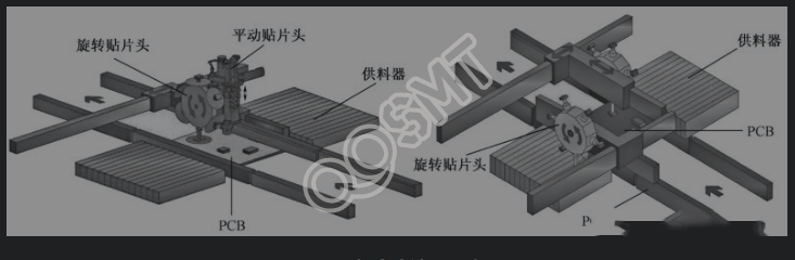
(1) Basic structure
The basic structure of the rotating head composite type is the same as that of the arch type. There are various platform-type basic structures such as single-arm single-head, single-arm double-head and double-arm double-head. The figure below is a schematic diagram of two of the structures.
(2) Circuit board transmission
The method of circuit board transmission is basically the same as that of the arch type. In order to improve the efficiency of conveying the board and the speed of the whole machine, some composite chip placement machines adopt the following methods.
① Dual-track transmission: When the width of the circuit board is narrow, two tracks can be used to transmit the circuit board at the same time. When the circuit board on one track is mounted with components, the other track can transport the circuit board.
② Single workbench and dual circuit boards: When the length of the circuit board is short, two circuit boards can be parked on the single-track workbench to reduce circuit board transmission time.
③ Intelligent Y-axis positioning workbench: In the traditional single-track conveyor board system, when the circuit board is narrow, the circuit board will be closer to the fixed edge of the conveyor track. For the dual-arm and double-head placement machine, since the placement head is in the Y direction The distance of movement is different, thus causing time loss. The intelligent Y-axis positioning worktable can move to the middle position according to the working conditions of both arms and heads, so that the movement distance of the two placement heads in the Y direction is equal to improve the efficiency of the machine.
(3) Mounting head structure
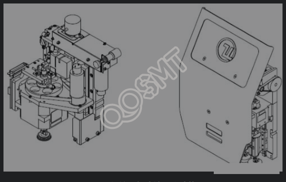
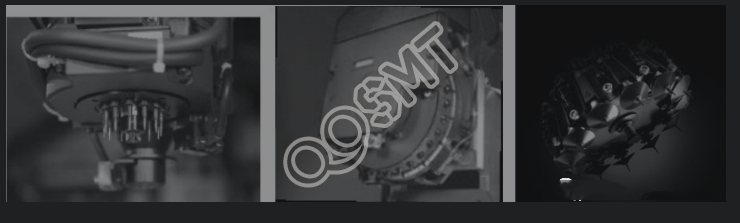
There are three types of rotary placement heads for composite placement machines (as shown in the figure below):
① One is a horizontally rotating placement head, similar to the turret of a turret-type placement machine, commonly known as a small turret;
② One is a vertically rotating SMT head, generally called a star-shaped SMT head and a lightning head;
③ There is also a placement head that rotates at a certain inclination angle.
The number of suction nozzles of the rotating placement head ranges from 8 to 30. Various rotary placement heads rotate once when sucking materials, and can pick up a number of components equal to the number of suction nozzles. After identification and correction, they are then mounted on the circuit board. The difference is that the first type of rotary placement head generally needs to be calibrated by an upward-looking camera fixed on the platform after the component is absorbed; the second and third types of rotary placement heads generally have a head on the placement head. Component identification camera, when the component pick-up and placement head rotates, the components can be identified and corrected. The first type of rotary placement head can pick up larger components by skipping adjacent suction nozzles. The size range of the components of the second and third types of rotary placement heads is limited by mechanical conditions.
(4) Feeder system
Most of the feeders of compound patch machines use electric feeders to improve the speed and accuracy of feeding. In order to increase the capacity of material types, many composite chip placement machines are equipped with dual-track feeders that can install two types of 8mm materials on the same feeder.
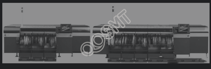
2. Double modular composite structure
The dual-module composite chip placement machine adopts a combination of modular structure and arch structure. Through the form of dual modules, the speed of the placement machine can be increased exponentially with only a small increase in length and area. It not only maintains the flexibility and high precision of the arch structure, but also has a modular structure. The structure is characterized by high productivity and efficiency.
(1) Basic structure
The dual-module composite structure is like two machines glued together (as shown in the picture below).
① One structure is a double working platform, 4 beams, and 4 placement heads. These 4 placement heads can all be equipped with high-speed placement heads to become an ultra-high-speed placement machine. You can also install 2 high-speed placement heads on work platform 1, and install a high-speed placement head and a multi-function placement head on work platform 2 to become a high-speed multi-function placement machine.
② Another structure is a double working platform with 3 beams and 4 placement heads. A high-speed placement head is installed on each of the two beams of the working platform 1 to become a high-speed placement module. A high-speed placement head is installed in front of a single beam of the work platform 2, and a multi-function placement head is installed behind it to become a multi-function module.
(2) Mounting head
There are two types of high-speed placement heads with dual-module composite structure: rotating placement heads and multi-nozzle parallel placement heads. There are two types of multi-functional placement heads: multi-nozzle parallel placement heads and single-nozzle placement heads. They generally have the function of automatically changing nozzles.
(3) Transfer board system
The transfer plate system of the double-module composite structure is roughly the same as the rotating head composite type, but there is usually a buffer area between the working platform 1 and the working platform 2 for the circuit boards to wait to enter the working platform 2.
(4) Feeder
Most of the feeders of compound patch machines use electric feeders. A tray-mounted feeder can also be installed on the work platform where a multi-functional patch head is installed.