BGA ball planting method and defective analysis
Jan 26, 2024
Preface
After the BGA has a welding problem, the replaced BGA itself is good and its function is no problem. If it is replaced, it is a very wasteful thing to directly scrap it. Although some customers stipulate that the manufacturing factory is not allowed to perform BGA ball planting operations by itself. , in fact, as long as the quality of ball planting is controlled well, it is a very considerable cost savings to ball ball the replaced BGA and reuse it. Therefore, today I will introduce to you the high success rate SMT BGA ball planting method, as well as the analysis and improvement of common defects. .
1. Introduction to BGA ball planting process
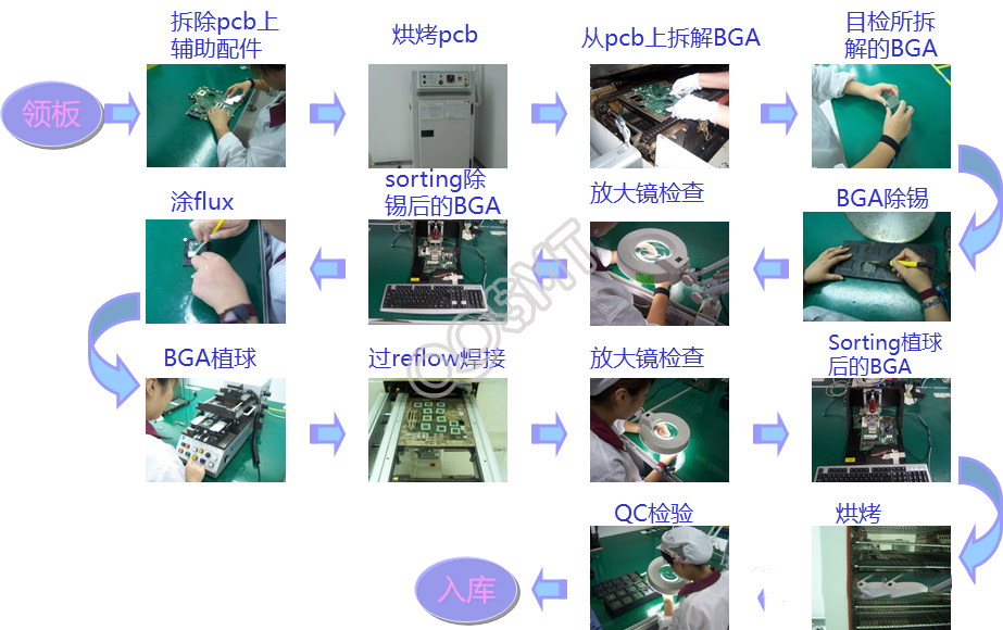
1. The BGA ball planting flow chart is shown in the figure below:
2. Key things to note during the process:
1) Pick up board: According to the BOM Release work order, after receiving the product from the defective product warehouse, it is necessary to confirm that the material number and quantity are correct.
2) Baking PCB: Baking conditions are 85 degrees Celsius, 8 hours
3) After disassembling and removing the tin, you need to clean the remaining flux on the BGA surface.
4) Check whether the BGA green paint and pads are scratched (peeling > 1/4 pad spacing). If this phenomenon occurs, no more balls can be planted.
5) Before the ball is planted, the BGA needs to be functionally tested to ensure that the BGA function is normal, and the appearance of the BGA must be inspected to see that there are no appearance problems before ball planting can be carried out.
6) Plant the ball and solder the solder ball through Reflow.
7) After the ball is planted, perform a functional test first. After the functional measurement is OK, bake it at 120 degrees for 24 hours. After baking, carry out vacuum packaging (vacuum packaging requires placing a humidity indicator paper card and desiccant)
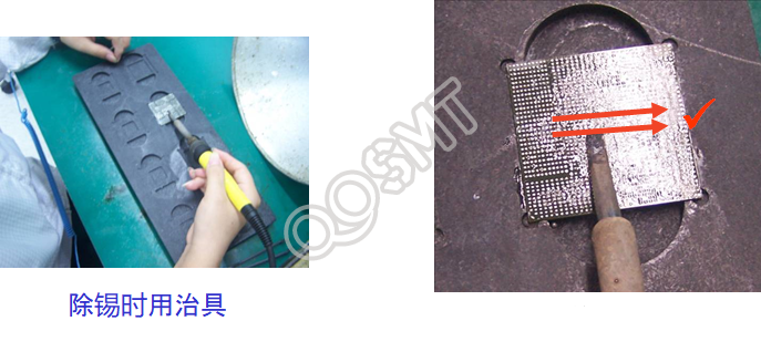
3. Tin removal operations:
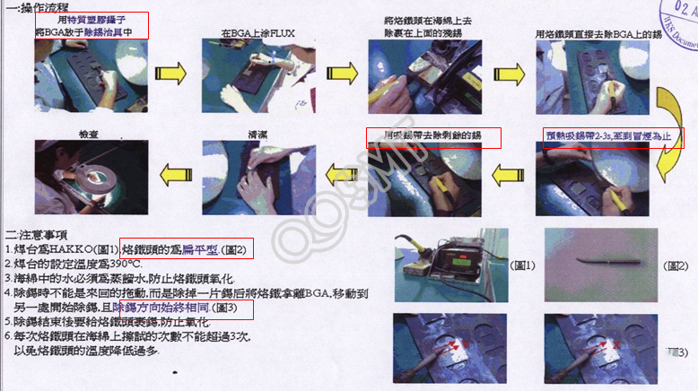
1) Operation process (as shown in the figure below)
-->Use a special plastic camera to place the BGA in the tin removal jig
--> Apply Flux on BGA
-->Put the soldering iron tip on the sponge to remove the residual tin.
-->Use a soldering iron tip to directly remove the tin on the BGA.
-->Preheat the soldering tape for 2~3 seconds until it smokes.
-->Use desoldering tape to remove the remaining tin.
-->Cleaning and inspection
2) Things to note:
---Soldering iron tip needs to be flat type
---Welding set temperature 390 degrees
---The water in the sponge must be distilled water to prevent oxidation of the soldering iron tip
---When removing tin, you cannot drag it back and forth. Instead, remove a piece of tin, take the soldering iron away from the BGA, and move it to another place to start removing tin. The direction of tin removal is always the same.
---After removing the tin junction, add tin to the soldering iron tip to prevent oxidation.
---The number of times the soldering iron tip should be wiped on the sponge should not exceed 3 times each time to prevent the temperature of the soldering iron tip from dropping too much.
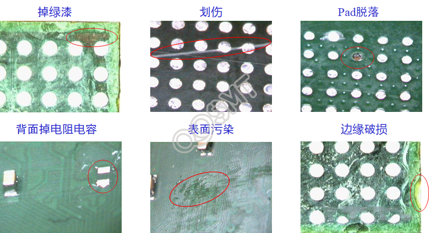
3) Remove tin defective items
Removing tin may cause defects as shown in the figure below,
4) Introduction to tin removal and fixing tools
Using the tin removal tool as shown below has the following advantages:
---After the BGA is fixed, it is not easily scratched by the soldering iron, and it is more convenient to remove tin;
---The parts on the back of the BGA are protected;
---Flux and tin cannot flow to the back of the part and cause contamination;
---Reduce pad shedding and green paint peeling off
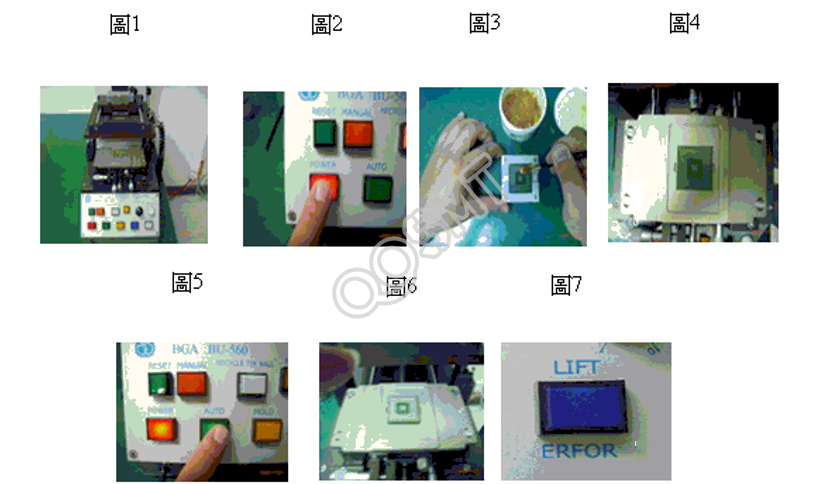
4. Ball planting operation:
1) Ball planting steps:
---Turn on the machine (as shown in Figure 1, 2), please note that new solder balls should be used
---Apply an appropriate amount of flux on the BGA ball mounting surface (as shown in Figure 3) Note: Use a special brush and special Kester R-253-5flux as a tool
---BGA polarity and ball mounting base polarity alignment (Figure 4)
---Press the AUTO button to plant the ball (as shown in Figure 5)
--- Take out the NHA after the balling is completed (as shown in Figure 7). Note: After the parts are balled, they can only stay on the base for 5 seconds. If the base drops, you can press the Lift key again to take out the parts (as shown in Figures 6 and 7).
---Check whether the removed parts are missing balls or the solder balls are offset, and make corrections
---After the ball planting is completed, a cycle operation ends.
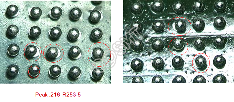
2. Analysis of common defects in BGA ball implantation
1. BGA reball shift