* We will reply you within 24 hours.

GKG GSE Solder Paste Printer SMD Stencil Printer
Frame size from 420×520mm to 737×737mm
PCB size from 50×50mm to 400×310mm
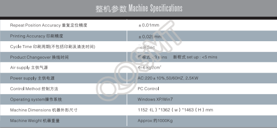
size: 1158*1362*1463mm
PCB size from 50×50mm to 400×310mm
size: 1158*1362*1463mm
Brand Name:
GKG
Model:
GSE
Condition:
New / Used
Payment Methods
GKG GSE SMT Stencil Printer Full Automatic-Good Price! Good Quality! Good Service!
Detailed Product Description
| Brand:: | Gkg | MODEL: | SMT Led Screen Printer |
|---|---|---|---|
| Weight:: | 600KG | Lead Time:: | IN Stork |
| Packing:: | BOX | CONdition: | Working |
| POWER: | 110V/220 | PAYMENT TERM: | T/T, Paypal, Westernunion Are All Allowed |
GKG GSE GT+ G8 SMT solder stencil printer from flasonsmt FULL ASSEMBLY Line machine
Quick Detail
Automatic solder paste printer is a high-precision and high-stability automatic vision printer. GKG company follows the development trend of the SMT industry. The new generation of automatic vision printer is synchronized with international leading technology, high-resolution visual processing. , High-precision drive system, Suspending adaptive scraper, precise plate positioning processing and smart frame clamping structure, compact structure, both accuracy and high degree of flexibility, provide customers with efficient, accurate printing required Function, more customers provide a prominent price.
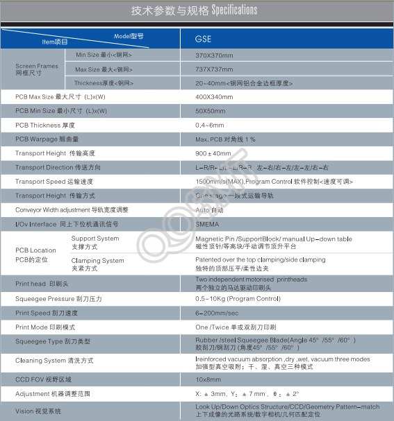
The main technical parameters:
(1) Printing accuracy: ±0.025mm
(2) Repeat accuracy: ±0.01mm
(3) Printing cycle: <7.5s
(4) Frame size from 420×520mm to 737×737mm
(5) Printable PCB size from 50×50mm to 400×310mm
Features:
1. The GKG dedicated manual adjustment jacking platform is simple, reliable, low-cost, and easy to adjust manually. It can quickly adjust the height of the PIN pin top of different thickness PCB boards.
2. Image and optical system New optical system - uniform ring light and high-brightness coaxial light, with brightness function that can be infinitely adjusted, making all types of Mark points can be well recognized (including uneven Mark Point) to adapt to tin, copper, gold, spray tin, FPC and other types of different colors of PCB.
3. Scraper system slide-type scraper system to improve operating stability and prolong service life
4. Cleaning System The new wiper strip ensures full contact with the stencil, and the large vacuum suction force guarantees that the solder paste remaining in the cell hole can be eliminated. The effective automatic cleaning function is achieved: three cleaning modes of wet and dry vacuum, and the software is free to use Set the cleaning mode and cleaning paper length
5. Steady steel net fixing structure
6. Perfect 2D detection system
Feature
| Product Name: | Smt GKG GSE full-auto Solder Paste Printer |
| Used for: | PCB Screen Printing Stencil Machine |
| Warranty: | 1 Year |
| Shipment | by air |
| Delivery Time: | 1-2Days |
| Our Main Market | Whole of the world |
Application
Production process
The production of the production process requires the preparation of the following types of data, and the preparation needs to be carried out in the following order.
PWB/Stencil Data → Printing Condition Data Input
(Printer Condition Data) → Check data input
(Inspection Data) →Cleaning Data →(Stinky)Supplementary data input
(Dispensation Data) The above data needs to be focused on the first item (PWB and screen data), the second item (print condition data) and the fourth item (cleaning data).
3, data input: use ALT to activate menu selection
2, Data Input
1. PWB/Stencil Data will pop up a PWB/Stencil data input screen. The data to be input in this screen is:
1) PWB ID ---- The code of the currently produced PWB.
2) PWB size (X, Y) --- The length and width of the current production PWB.
3) Layout offset (X, Y)----The deviation of the current production PWB (generally refers to the lower right corner of the PWB).
4) Thickness (Z) ----- The thickness of the current production PWB board.
5) Stencil ID ---- The code of the currently used stencil.
6) Stencil size (X, Y)--- The length and width of the currently used stencil.
7) Printer layout standard----Select the mode of deviation standard of current printing.
8) Origin offset (X, Y) ----- Deviation between the PWB reference point and the stencil reference point.
9) PWB type ----- Select the PWB type in the selection box.
10) BOC mark NO.1 (X, Y) - PWB and the deviation of the screen correct the coordinates of the first identification point.
11) BOC mark NO.2 (X, Y) - - - Deviation of PWB and net plate Corrects the coordinates of the second identification point.
12) The asterisk following SOC mark NO.1, SOC mark NO.2, and BOC mark NO.1 and BOC mark NO.2 indicates the identification information of this identification point.
Adjustment method:
1. Move the cursor to the asterisk of the corresponding recognition point and press the "Camera" key on the HOD (Handheld Operating Device).
2. First adjust the shape of the recognition point, align the recognition frame with the surrounding of the recognition point, press "Enter" key to confirm and use the arrow keys to select the shape of the recognition point, select the corresponding shape, and then press "Enter" to confirm.
3. Use the arrow keys to adjust the sensitivity of the recognition. After the adjustment, press the "Enter" key to confirm.
4. Use the arrow keys to adjust the identified range. First adjust the upper left and then adjust the lower right. After the adjustment, press the "Enter" key to confirm. After compiling the above data, you can start to compile the print condition data. You can use the ALT key to activate the menu selection 3, Change 2Printer Condition Data or directly press "F6" to switch to the print condition data creation screen.
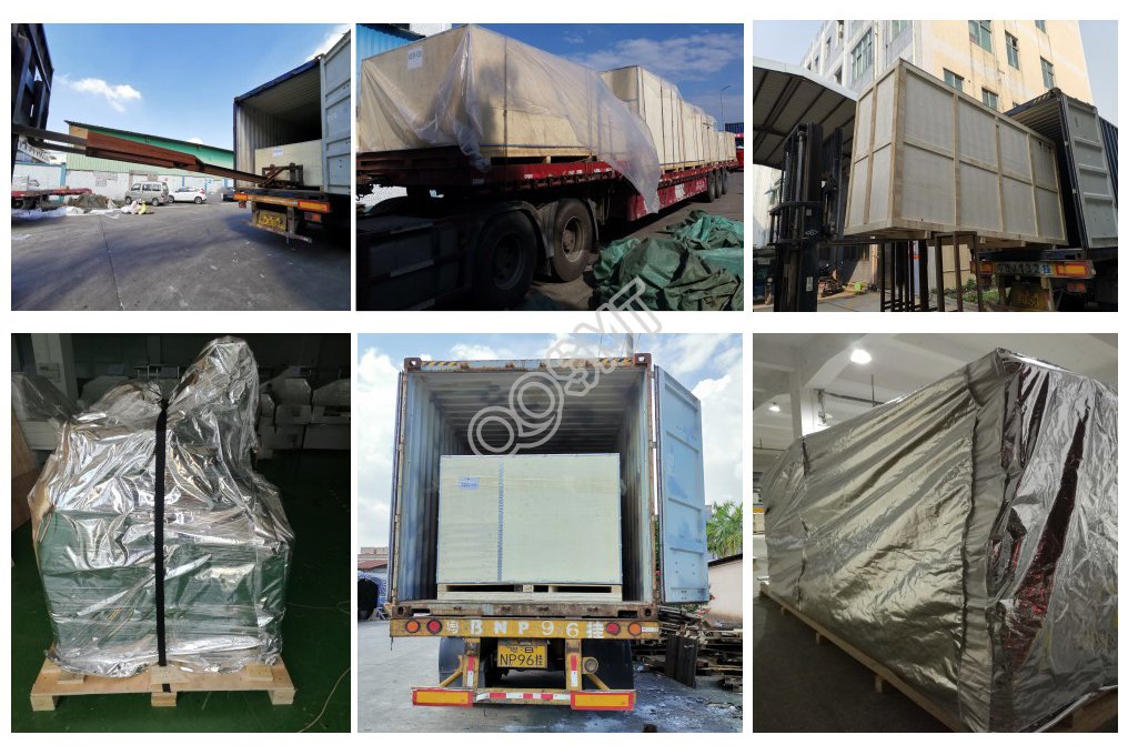
Ensure your ordered products are always safely packaged fast delivery to your hands