Detailed explanation of the detection and sensing system of SMT placement machine
Jan 22, 2024
Preface
Relevant parts of the machine have sensors with different functions to ensure machine movement coordination and realization of functions. A sensor is a device or device that can sense a specified measured object and convert it into a usable signal according to certain rules. It usually consists of a sensitive element and a conversion circuit. A sensor is a detection device that can sense the information of the object being measured, and can convert the detected information into electrical signals or other required forms of information output according to certain rules to meet the needs of information transmission, processing, and storage. , display, recording and control requirements. It is the primary link to realize automatic detection and automatic control.
1. Sensors in the placement machine
The placement machine is composed of many parts. Its operating conditions require many parts to operate in a normal state. How do you know that each component is under normal operating conditions? Sensors fulfill this mission. The status of each component is detected through sensors, and then the information is transmitted to the control part for display, telling the operator whether the equipment can be operated. If the equipment cannot be operated, an error message will be displayed, and the operator will follow the prompts to troubleshoot so that the equipment can operate. normal operation.
The placement machine is equipped with various forms of sensors, mainly force and optical sensors, which play an information collection role in all aspects of the placement machine's work. As the automation and intelligence of placement machines increase, the types and number of sensors will increase. Generally speaking, the more types and numbers of sensors in the machine, the higher the level of automation and intelligence of the placement machine. The following table shows the types and functions of sensors currently commonly used in chip placement machines.
2. Pressure sensor
The air pressure system of the placement machine includes various cylinder working pressures and vacuum generators, all of which have certain requirements for air pressure. When it is lower than the equipment specifications, the machine cannot operate normally. The air pressure sensor always monitors pressure changes. Once abnormal, it will alarm in time to remind the operator to deal with it.
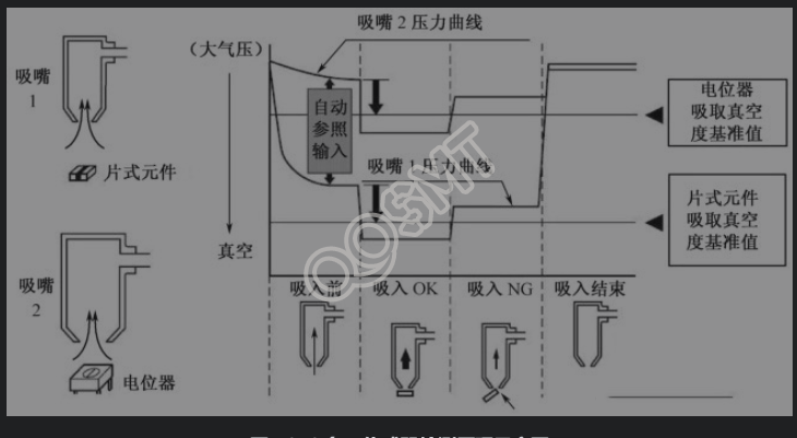
The suction nozzle on the patch head relies on negative pressure to suck components. Therefore, changes in negative pressure reflect the suction of components by the suction nozzle (as shown in the figure below). If there are no components in the feeder, or if the components are too large and stuck in the material package, the nozzle will not be able to suck the components; or if the nozzle picks up the components, but the components are sucked incorrectly, the suction nozzle pressure will change. , by detecting pressure changes, the placement situation can be controlled. Of course, if the negative pressure is not enough, the suction nozzle will not be able to suck the components, or even though the components are sucked, they will fall due to the force of movement during the movement of the placement head. These abnormal conditions are detected by the negative pressure sensor. monitor. If it is found that the components cannot be sucked or cannot be sucked, the system will alarm and remind the operator to replace the feeder or check whether the suction nozzle negative pressure system is blocked.
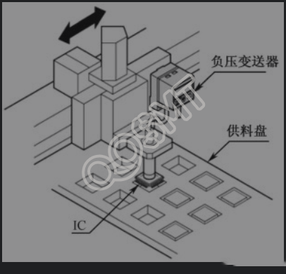
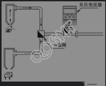
At present, the new negative pressure sensor has been miniaturized. The negative pressure sensor is integrated with the conversion and processing circuit to form an integrated component. This component that integrates the sensor with the conversion and processing circuit is usually called a transmitter, and the transmitter outputs a standard electrical signal (0 to 5 V voltage or 4 to 20 mA current). The small negative pressure sensor can weigh less than 70 g, so it can be mounted directly on the chip head (as shown in Figure 1 below). Since each nozzle picks up and mounts in sequence when the multi-nozzle placement head is working, the two nozzles can also share a negative pressure sensor through the solenoid valve (as shown in Figure 2 below).
Figure 1 The negative pressure sensor is directly mounted on the chip head
Figure 2 Two nozzles share a negative pressure sensor
3. Position sensor
The transmission and positioning of printed boards includes PCB counting, real-time detection of the movement of the placement head and workbench, and the movement of auxiliary mechanisms. They have strict requirements on position, such as the origin positioning of the placement machine, or for the safe operation of the machine, usually in There are photoelectric sensors in the sports area, which use photoelectric principles to monitor the running space to prevent damage caused by foreign objects. These are achieved through various forms of position sensors. The following takes Universal's FLEXJET head placement machine as an example to illustrate the two position sensors of the OTHC camera on the placement head, as shown in the figure below.
In addition, the Z-axis of the FLEXJET head also has a Home sensor, which senses that the Spindle has returned to the upper position in the Z-axis direction; the Read Head reading head fixed on the X-axis and Y-axis beams works together with the optical ruler of the corresponding axis to sense Detecting the position of the axis is also a position sensor.
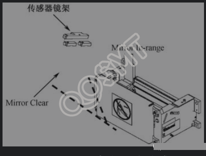
• Mirror In-range/Clear: (Sliding mirror in-range/clear) sensor.
• Mirror Clear: This sensor is used to ensure that the lens has safely moved out of the way during the movement of the Spindle, and the Mirror In-range sensor ensures that the sliding lens is in place for taking pictures. The length of the wire must be adjustable so that when the mirror clutch is activated, the lens is pulled all the way down until the In-range sensor is triggered; when the mirror clutch is not activated, the connecting wire must be long enough to allow the lens to reach and activate the Mirror Clear sensor.
The area detection sensor is actually a position sensor. For example, for various types of placement machines, the X-Y positioning system of the machine has a working range. When it is exceeded, an error will occur or even the machine will be damaged. Therefore, it is necessary to set limit switches at the ends of the X-axis and Y-axis beams. When the movement of the axis exceeds the working range, the machine will generate a limit error and stop moving, thus functioning as area detection.
1. Press-fit on-off electrical sensor
Through mechanical contact, the sensor connects or disconnects the circuit and detects whether the object reaches the specified position. For example, the safety cover closes the sensor and the component supplies some of the safety protection devices (Z-axis side safety interlock and box float sensor).
2. Photoelectric position sensor
Photoelectric position sensors are often also called photoelectric switches. According to the position of the light source and receiver, there are three common photoelectric position sensors:
(1) Separation of light source and receiver
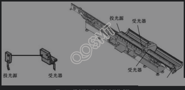
The working principle of the sensor with separate light source and light receiver is that during normal operation of the equipment, a beam of light is emitted by the light source, which is received by the light receiver. When an object blocks the light and the light receiver cannot receive the light, the sensor will store this information. Transmitted to the controller for display and alarm.
This kind of sensor is used to detect whether the feeder is installed in place. It is usually installed at both ends of the feeder base, as shown in the figure below.
(2) The light source and receiver are integrated
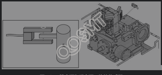
Its working principle is that when the specified part of the moving part (such as the placement head) blocks the light, the sensor receives the information of the component (the placement head), transmits this information to the control part, and tells the machine that this part is ready (as shown below) shown).
This type of sensor is commonly used to detect whether the placement head is in place, whether each mechanical part returns to zero, or whether the mechanical position reaches the limit position, etc.
(3) The light source and receiver are on the same plane
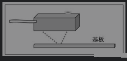
The working principle of the light source and the light receiver on the same plane is reflective detection, as shown in the figure below. When the object to be measured reaches the detection position, the light emitted by the light source is reflected to the light receiver, and the sensor output state changes to achieve the purpose of position detection. .
When the placement machine is working, when the substrate passes the substrate transportation deceleration sensor, the substrate begins to decelerate. When the substrate reaches the detection position, the stopper forward limit sensor gives information, and the stop cylinder moves downward to stop the substrate. At the specified position, the workbench rises, the stop cylinder goes up, the stopper returns to the limit, the sensor gets the information, and the patching starts; when the patching is completed, the workbench drops, and the substrate sending information is given to send the substrate out.
3. Z-axis control sensor of patch head
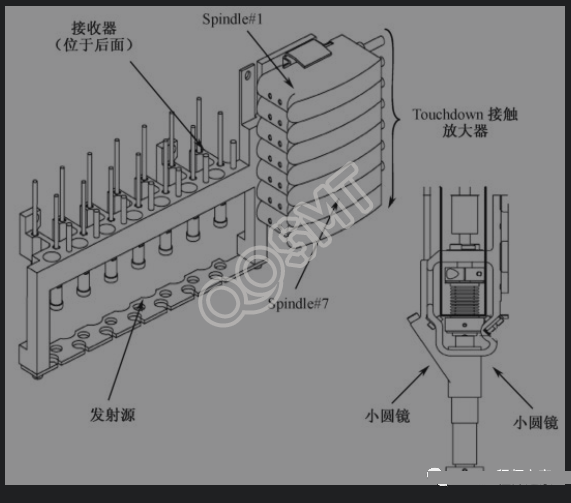
With the improvement of placement speed and accuracy, the requirements for the "placement force" of the placement head to place components on the PCB are getting higher and higher. This is commonly referred to as the "Z-axis soft landing capability". Z-axis soft landing is achieved with the help of the sensor installed on the patch head and the load characteristics of the servo motor. Machine software uses sensors to sense. The following uses the Global FLEXJET patch head Touchdown sensor as an example to introduce Z-axis motion control.
The new Touchdown sensor is used on the FLEXJET2/FLEXJET3 placement head to control the smooth contact of the nozzle with the circuit board, feeder and nozzle. The luminosity returned to the receiver is not as important as the consistency of the light, this is because now it is the change in luminosity that is being looked for and the sensor is locked at 0.100" above the desired end of contact (to avoid errors during acceleration). At this point, The optical density of the sensor is captured during Touchdown contact and when the density reaches 80% of the locked value, the software considers contact to have occurred. When the small round mirror of these Touchdown sensors becomes dirty, the sensor is very forgiving because the acquisition optical density determines When contact occurs. The small round mirror thus reduces the optical density, so the small round mirror also needs to be cleaned but less frequently. The working diagram of the Touchdown sensor is shown in the figure below.
4. Laser and vision sensors
1. Laser sensor
Laser sensors have been widely used in placement machines. Its biggest advantage is its fast response speed, so it can achieve "flying alignment" and increase placement speed. The laser sensor can accurately reflect the position and orientation of the component and determine the coplanarity of the device pins; the laser sensor can also identify the height of the device, which can shorten production preparation time. At the same time, it has the ability to handle components of various shapes and sizes. However, even the most sophisticated laser systems cannot measure pins and pin spacing.
The working principle of the laser sensor is shown in the figure below.
2. Vision sensor
Currently, the commonly used image sensor is a Charge Couple Device (CCD), which is divided into two types: linear array CCD and area array CCD. The former is used for the measurement of size and displacement, and the latter is used for the transmission of plane graphics and text. At present, area array CCD has been used as digital cameras (DC), digital video cameras (DV), various digital cameras and industrial vision systems. The camera used in the placement machine to identify PCB benchmarks and detect components is used in industrial vision systems.
(1) How CCD works
CCD is composed of many photosensitive pixels, each pixel is a MOS (metal-oxide-semiconductor) capacitor, as shown in the figure below. A layer of SiO2 is formed on the P-type silicon substrate through oxidation, and then a metal layer (polysilicon) is evaporated on the surface of SiO2 as an electrode. The majority carriers in P-type silicon are positively charged holes, and the minority carriers are negatively charged electrons. When a positive voltage is applied to the electrode, its electric field can repel or attract these carriers through the SiO2 insulating layer. As a result, the positively charged holes are repelled away from the electrode, and the negatively charged electrons are attracted to the surface close to the SiO2 layer. This phenomenon forms a trap for electrons. Once electrons enter, they cannot come out, so it is also called an electron potential well.
When a beam of light is projected onto the MOS capacitor, the photon passes through the polysilicon electrode and SiO2 layer and enters the P-type silicon substrate. The energy of the photon is absorbed by the semiconductor, generating electron-hole pairs. At this time, electrons are attracted and stored in the in the potential well. The stronger the incident light, the more electrons are collected in the potential well, thus achieving the conversion of light and electricity. The electrons in the potential well are in a stored state, and will not be lost within a certain period of time even if the illumination is stopped. This realizes the memory of the illumination.
(2) Structure of area sensor
Area sensors are often called image sensors. As shown in the figure below, an area sensor consists of a two-dimensional array of photodiodes. In order to extract the charge of each photodiode, a vertical CCD that performs charge transfer is arranged in the vertical direction of the figure. The charge from the photodiode is read by the vertical CCD through the control of the field effect transistor (transfer control gate). The charges transferred to the vertical CCD are transferred to the horizontal CCD for horizontal transmission, and finally the signal is read out from the MOS field effect transistor. The pulse to read out the charge of each photodiode consists of three parts, namely the pulse applied to the control gate, the pulse applied to each CCD pixel and the combined control pulse applied to the gate of the output MOS field effect transistor.
In the example introduced above, the photodiode part (photosensitive part) and the CCD part (transfer part) are made in one body on the semiconductor substrate. This charge transfer method is called inter-line transfer method. . This method is conducive to high-speed image processing. However, since the non-photosensitive part of each pixel occupies a large area, the photosensitivity efficiency is not high. Corresponding to the interline method, the method in which the photosensitive part and the transfer part are produced separately is called the frame transfer method.
(3) Combination with image processing technology
The camera can only convert the two-dimensional light intensity distribution into an analog electrical signal that continuously changes with time (called an image signal), but this alone is not a visual signal that can be perceived by human visual organs. In order to obtain visual signals, computers must be relied upon for further signal processing. Usually image signals are converted into digital signals, which are easily stored in the computer's memory and then image processed as needed.
The visual inspection system of the placement machine has a dedicated image processing system, which converts it into digital signals based on information such as pixel distribution, brightness and color. The image processing system performs various operations on these signals to extract the characteristics of the target, such as area, quantity, and location. and length, and then output the results according to the preset tolerance and other conditions, including size, angle, number, qualified/unqualified and presence/absence, etc., to realize automatic identification function.