Do you really know the placement speed of SMT placement machine?
Jan 23, 2024
Preface
Placement speed is one of the most basic characteristics of placement technology. It is also the most sensitive, representative and easily comparable parameter among the performance indicators of placement equipment. In many cases, it is also one of the indicators of the grade and level of the placement machine. Important symbols are important performance indicators in the evaluation, selection and use of placement machines.
1. Nominal and actual placement speed
Mounting speed refers to the placement machine's ability to mount components per unit time. It is generally expressed in terms of the number of mounted components per hour or each component placement cycle, such as 60,000 points/h or 0.06 s/component.
1. Nominal speed of placement machine
Usually, among the parameters of the placement machine, the placement speed is only the theoretical speed, which is calculated based on the minimum pickup time of the nozzle, the shortest moving distance from the pickup position to the placement position, and the minimum placement distance and other ideal conditions. Theoretical speed; and it is only the theoretical time for component placement, and does not include auxiliary time such as transfer time and preparation time, as shown in the figure below.
At present, there is no accurate definition and measurement method of placement machine speed in the industry. Now placement machine manufacturers use an ideal method to measure speed data, which does not include any external factors, that is, it does not consider the transportation and positioning time of the printed board. The size of the board, the type of components and the mounting position, etc., only require a certain number of components of one type (for example, 120 chip components or 10 QFP packaged ICs) to be mounted on the sample board in a regular arrangement, as follows As shown in the figure, then calculate the average time for each component and give the "placement speed" in terms of how many pieces per hour or how many seconds per piece, for example:
• Placement speed - 36000 cph (Chip Per Hour or Components PerHour);
• Placement speed - 0.1 s/c (seconds to place each component Second/Chip or Second/Components).
Since the mounting speeds of chip components and IC packages are very different, some more professional suppliers will give the mounting speeds of the two separately. Usually chip components are measured in "cph", while IC packages are measured in "s/c". If there is no distinction between chip components and IC packages, it refers to the placement speed of chip components.
No matter what format and unit the supplier gives, the placement speed is the theoretical speed, also known as the nominal speed. It has only a reference significance for relative comparison and is different from the number of components that can be mounted per shift in actual production (actual speed). Placement productivity) is far from the same.
In addition, the indicator "Cycle Speed" (Cyclc Ratc) or "Test Ratc" (Test Ratc) is also used when examining placement speed and comparing different machines. It is the most basic measurement parameter of the speed of the placement machine. It is similar to the theoretical speed above, except that the parts have not actually been placed and the machine is still in idling mode. This speed value does not involve the effects of component picking, centering, and placement, so it is faster than the equivalent theoretical speed. Although the cycle speed is a useful indicator for comparing the mechanical drive efficiency of the machine, it has little practical significance to the user, so it is generally not provided in the parameters of the placement machine.
2. Actual placement speed
Obviously, in actual placement production, it is impossible to have only one kind of component, nor to arrange it in a regular array. In fact, additional time is required and there are many factors that affect the placement speed.
In actual patch production, the time that needs to be considered is as follows.
① Circuit board transfer and positioning time: The mounted circuit board is transferred from the work surface to the lower machine or waiting position, and the waiting circuit board is transferred from the upper machine or waiting position to the machine work surface. Usually the actual transmission takes 2.5 to 5 s, and some special devices can reach 1.4 s.
② Circuit board reference point correction time: Due to the transmission of the circuit board, the warpage of the circuit board and the mounting accuracy requirements, using the reference point positioning on the circuit board is the best way. Generally speaking, one reference point can only correct the deviation in the X and Y directions of the circuit board; two reference points can correct the deviation in the X and Y directions of the circuit board and the angle deviation; three reference points can correct the X and Y direction deviation of the circuit board. Deviation and angle deviation, as well as warping deformation caused by double-sided panels after one side has been reflowed.
③ Nozzle replacement time: Since there are various components on the printed circuit board and require different nozzles, the nozzles on the placement head often cannot absorb all types of components. Therefore, the general platform-type machine design has Automatic nozzle replacement function.
④ Component feeding and suction time: Generally, components should be fed in place before being sucked. However, when continuously sucking on the same material station, if the feeding time of the next material is longer than the time of replacing another suction shaft to suck the material, the placement The first thing you need to do is wait for component feeding. The time for component suction includes the movement of the nozzle over the component, the suction nozzle moving to the component suction position driven by the Z-axis, contacting the suction nozzle, the vacuum opening of the suction nozzle, and the return movement of the suction nozzle with the component driven by the Z-axis. The time required for height.
⑤ Worktable moving time: For turret-type machines, it refers to the time for the X and Y worktables to drive the printed circuit board from the previous position to the position where it will now be mounted; for platform-type machines, it refers to the X of the cantilever , the time it takes for the Y drive axis to drive the placement head to move from the previous position to the current position to be placed.
⑥ Component recognition time: refers to the time when the component passes through the component recognition camera and the camera captures the component image. For turret-type machines, since the turret rotates with a certain frequency and the time for photographing a single component is less than the time for component picking and placement, the component recognition time for turntable-type machines is basically negligible.
⑦ Component placement time: The suction nozzle brings the component to the top of the mounting pad. The suction nozzle is driven by the Z-axis and drops to the height of the patch and contacts the solder paste on the pad. The vacuum of the nozzle is closed and leaves the patch. Height, the sum of the time required for the suction nozzle to blow open to ensure that the components are not brought up as the suction nozzle leaves, and the time required for the suction nozzle to return to the original height.
⑧ Waiting time for placement head replacement (multiple placement head machines).
In short, the actual placement speed of the placement machine is much lower than its marked theoretical speed. Depending on the number, distribution, type and type of patch components on the circuit board, as well as the characteristics and form of the patch machine, the actual mounting speed of the patch machine is usually only 50% to 75% of the theoretical speed.
2. Calculation of placement speed
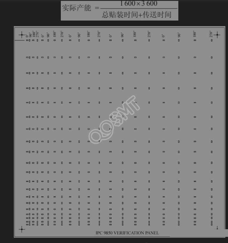
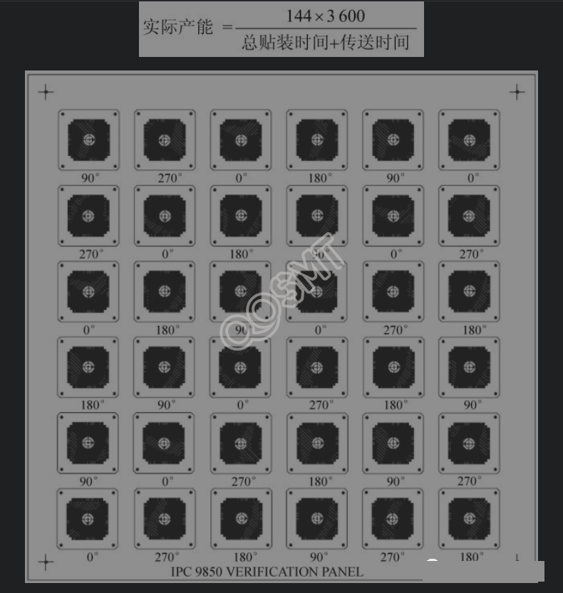
In view of the above reasons, each manufacturer of placement machines will use self-defined parameters and methods to express the production capacity of their equipment. The IPC Organization's Placement Equipment Subcommittee has used IPC9850 to conduct detailed analysis of the equipment's production capacity and process capabilities since 1995. , unified definition.
In the formula, the time unit is seconds, and the production capacity unit is CPH (Chips Per Hour).
In IPC9850, a standard placement verification panel (PlacementVerification Panel, PVP) with a length and width of 200mm and a reference point at each of the four corners is used to test the process capability and productivity of the placement machine. One of the following 5 components can be used in the inspection:
• 36 QFP—100;
• 30 QFP—208;
• 100 BGA—225;
• 80SOIC16;
• 4001608C (Capacitors).
In the productivity inspection of the placement machine, the general productivity inspection of the high-speed placement machine adopts the continuous mounting of 4 PVPs. The components are 1608C. A total of 1600 1608C components need to be mounted on the 4 boards. The component distribution is shown in the figure below.
In the productivity inspection of the multi-function placement machine, 4 pieces of PVP were also continuously mounted. The components generally use QFP-100. A total of 144 QFP-100 components need to be mounted on the 4 boards. The component distribution is shown in the figure below.
3. Installation rate and ways to improve it
1. Installation rate
(1) Define the implementation rate
It refers to the ratio of theoretical placement speed to actual placement speed, generally expressed as a percentage. It is a basis for measuring and comparing placement efficiency when selecting a placement machine. The installation rate is also called "placement efficiency". In order to avoid confusion with "placement rate", it is more reasonable to call it the installation rate.
The formula for calculating the implementation rate is
Installation rate = actual placement speed/theoretical placement speed
Among them, the actual placement speed is measured through experiments.
For example, we mount 10 circuit boards on two different placement machines A and B respectively. There are 35 types of 300 components on this circuit board. The actual placement result is that the placement time of A and B is 375. s and 10000 s, and the theoretical speeds of A and B placement machines are 0.1 s/c and 0.2 s/c respectively, then
A placement machine: actual placement speed = 375/3000 = 0.125, installation rate = 0.1/0.125 = 0.8, or 80%;
B placement machine: actual placement speed = 10000/3000 = 3.333, installation rate = 0.2/3.333 = 0.6, or 60%.
(2) Factors affecting the implementation rate There are many factors that affect the implementation rate, mainly the following points.
There are many factors that affect the implementation rate, mainly the following points.
① Type of placement machine.
From the analysis of the placement principle, the actual placement speed of a turret-type machine with multiple suction nozzles should be faster than that of the arch-type placement machine because the placement head does not move and the components are picked up, inspected and placed simultaneously. The installation rate is also high; while the rack-mounted placement machine has a relatively low installation rate because it picks up components, detects and places them step by step. Obviously, the arch-type multi-head machine has a higher installation rate than the single-head machine, while the composite type is somewhere in between; this analysis is basically consistent with the actual test results.
② PCB complexity.
The more component types and polarity components there are, the lower the implementation rate.
③ The level of design for manufacturability (DFM).
Experienced, high-level manufacturability design can increase implementation rates by more than 10 percentage points. PCB layout and component arrangement will affect actual placement speed.
④ Component placement performance.
Component surface quality and geometric size consistency will affect actual placement speed.
⑤ The size of the production batch.
⑥ Production organization management and machine failure maintenance level.
2. Ways to increase the speed of the placement machine
In view of the importance of placement speed, manufacturers are doing everything possible to improve the speed of placement machines. The main methods currently used to increase the speed of placement machines include the following.
(1) Improvement of the placement machine structure
• Use dual tracks to realize PCB placement on one track and board delivery on the other track, reducing PCB transportation time and placement head standby time;
• Multi-placement head combination technology, currently including double-head and 4-head structures;
• The arch structure adopts simultaneous driving at both ends to prevent the effect of cantilever beams and reduce mechanical stabilization time;
• Combined (or modular) multi-unit structure emphasizes placement speed per unit area.
(2) Mounting head and nozzle technology
• Lightning placement head;
• Multi-nozzle structure – up to 30 nozzles on one placement head;
• High reliability and high adaptability nozzle, capable of mounting components from 0201 and 01005 to 30mm×30mm QFP components; • Quick replacement nozzle.
(3) Motion drive and linear motor technology
• Using fuzzy control technology, the movement process is divided into three stages of control, namely "slow-fast-slow", changing in an "S" shape, so that the movement becomes both "soft" and fast;
• The X-axis operation adopts a dual servo motor drive system with a fully synchronous control loop to speed up the movement;
• Adopts a patented linear motor with high positioning accuracy and high repeatability, high speed and acceleration, fast and stable (up to 55 ms), small operating current, and high-precision control.
(4) Rapid detection technology
• Cooperation of laser and CCD applications;
• Dual cameras - separate detection of chip components and large-size ICs;
• Fast image acquisition and conversion circuit;
• Advanced image processing and computing software.
(5) Feeder technology
• Intelligent feeder feeding method reduces component replacement time and manual errors;
• Changing materials without stopping the machine;
• Dual belt feeder;
• Large-capacity feeder, some placement machines can reach a capacity of 256 8mm feeders;
• Interchangeable trolley;
• Try to use tape packaging for devices that use a lot of materials;
• Efficient bulk feeding.
(6) Optimize the placement program optimization principles:
• Minimize the number of nozzle changes;
• The shortest distance for picking up and placing chips;
• Multi-head placement machines should also consider picking up the largest number of chips at the same time;
(7) Operate the machine in accordance with safe operating procedures and improve the maintenance level of the equipment
(8) Software technology
• Various forms of PCB files can be directly optimized to generate placement program files, reducing manual programming time;
• Adopt offline programming when producing multiple varieties and small batches;
• Machine fault self-diagnosis system and large-scale production integrated management system;
• Intelligent operating system.